Quantcast
Channel: Desert Home
Viewing all 218 articles
Browse latest View live

After a Long Testing Period, Moving Forward With My Temperature Sensor

$
0
0
A while back I came up with a battery operated temperature sensor that sent its data over my XBee network <link>. This little device has been sitting beside my bed for a long time now and works well. It has had it troubles over the months that I had to fix, but that was the point: make sure it works before moving it into a bigger project. Also, I use it to turn off my bedroom lights from the bed and have coupled it into turning off other things to be sure they're ready for the night as well.

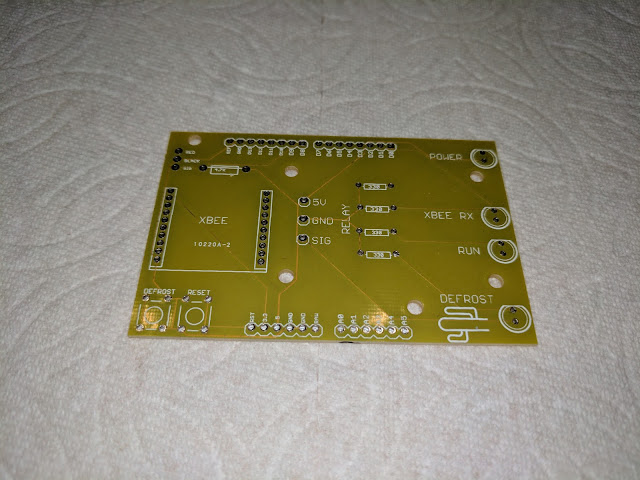
I decided it was time to make some more of them, but the thought of hooking up thirty or so little fiddly wires on a protoboard kept me from actually doing it. What I needed was a custom PC board. I've designed a board before for a charger I came up with for the various lead acid batteries around the place <link>, but that project died when I found a really good battery maintainer to use commercially available. I still have one of the boards running, but it's only monitoring the battery voltage, not charging anymore. I may get back to that project at some point and come up with a simple battery monitor replacement, but right now I need an easier assembly technique and a custom board sounds like a great idea.

I dragged out Eagle <link> that had been hiding somewhere on my machine for months and updated it (of course) and started trying to use it again. Needless to say, I had to find a couple of tutorials to get me started again. I took the schematic for the sensor and came up with a board that looked like it would work, let it sit for a couple of days, revisited it and made a couple of changes then sent it off to OSH <link> which is SparkFun's old PC board service they farmed out.

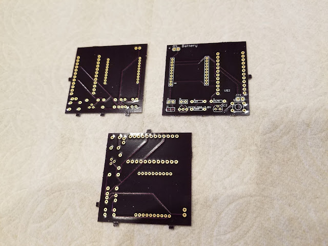
I got the boards back a couple of days ago and assembled one of the three to see if it would work.


They're two inches square and purple. They're also thinner than I'm used to seeing, but that doesn't really seem to matter; they are strong enough to use.

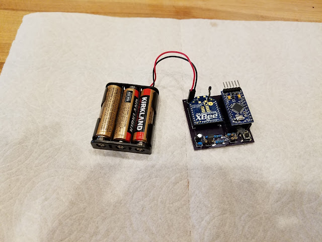
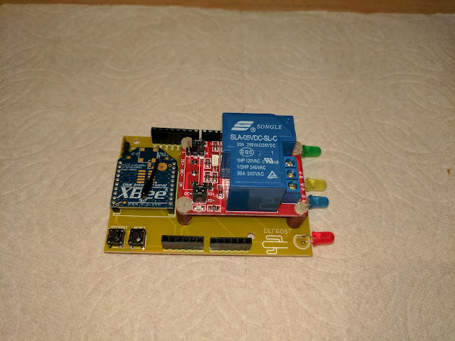
When I got one of them loaded with components:


Yep, I'm still using the cheapest batteries I can find. I put the XBee and the Arduino side by side instead of vertically to meet a different form factor I couldn't try with the prototype. I'm still mounting all the active components in sockets so I can trade them out if necessary. I was lucky, it worked first try.

Well, that's partly a lie. The circuitry was fine and everything connected up OK, but I put the wrong profile on the XBee and it took some head scratching to find out what happened. Note to self: pay attention to what you name the profiles.

I went and got one of my famous rubber bands and packaged it up:


There's some things I might do differently on my next order, and in general. For example: if I flip the ftdi connector over to the other side of the Arduino it would make the height shorter and maybe easier to mount in a permanent enclosure. It might be good to actually include some holes for mounting the thing; I totally forgot that part. I did think of things like a place for a connector for the switch, but I put it too close to the switch to be easily connected. Lastly, more labels on the board. I had trouble telling which capacitor went where. Labels like C1, and C2 didn't tell me much and I had to keep looking at the schematic to assemble it. Of course, if you already have an example made, this problem doesn't exist, so maybe I'll just keep a good picture of it on my phone to refer to later.

The period from creating the artwork for the board and getting it back was long enough that I even forgot which way I pointed the Arduino and XBee. Sad I didn't put an arrow or something on the silk screen for the board. But, I guess we have to learn some things the hard way. At least I do. Nevertheless, IT WORKED !

I'm actually pretty happy with how it turned out. The idea of taking major components that I can buy for the most complex parts and just mounting them as modules on a board that interfaces them and has the interface components worked really well. I don't have to stock all the parts for a bare bones Arduino, I just use a cheap Arduino Pro Mini. I don't have to stock some radio parts or fiddle with RF alignment, I just use an XBee. The only parts are simple to install ones and not many of them.

Now, I have a bunch of work to do. I already had code on my Raspberry Pi to update the data base when a new temperature sensor appeared and that worked well, so I'm saving readings from two of them now (the prototype and the new one), but I'm not doing anything with it. The real objective for these is to put one in each strategic place around the house and use them to control the house temperature.

The plan is to measure the temperature and intelligently control the air handlers and compressors of my two heat pumps to adjust for warm spots in the summer and cold ones in the winter. I want to get out of the tub after a long soak in the winter and NOT freeze my butt off. I can use the air handlers to distribute warm air from the hot side of the house in the winter, and just reverse that in the summer.

I won't have thermostats at all, I'll network the entire thing and control it with an HTML interface. I may still leave a display up in the place of the thermostats since people expect to be able to look at one, but it won't have any buttons. OR, I may put a cheap tablet up on the wall with a browser running to control the entire house with.

This will mean a control board at each air handler so I can control various relays that work the fan, compressor and reversing switch that hooks into my XBee network as well. But hey, I talked a bit about that already <link> so I won't bore you until I actually start that part.

I'll need at least three more boards, and I may make the changes I talked about in the second order, but thinking about it, the changes are trivial and I can live without them. I also have other ideas about using something like this to monitor the moisture in the soil of my two new fruit trees, and as mentioned earlier, the state of the tractor batteries in the barn. See, I can put any sensor on the device and have it transmit whatever I want to my network. I may look at a motion sensor for the driveway to tell me when someone drives up. Doing that without wires would be really cool. That would mean some changes to the board for the different uses, but that also means that I GET TO MAKE CHANGES TO THE BOARD as well as try out some new sensor and code.

I'm definitely going to need some more batteries.
I Got One of Those New Fangled Amazon Dot Things

$
0
0
Obviously, this is part 1.

Yes, I took the plunge and bought an Amazon Dot before it was available and waited patiently for the release date for it to arrive. When it came in, I did the usual, "Alexa, tell me the weather.""Alexa, what time is it?""Alexa, how tall is Scarlett Johansson?" You know, the usual.

Then, I got out the laptop and started looking at how to connect it to my house.

Let me tell you, this thing is really, really cool, but it's also the most frustrating device I have worked on in quite a while. I literally spent hours and hours on the web trying to figure out Amazon's amazingly complex and poorly documented interface to IOT (internet of things). I tried a large number of examples and tutorials out there with a singular result: they didn't work. I knew it was possible, there are youtube videos that prove it, but not a single one of them worked for me. I wrote, copied, stole thousands of lines of code and didn't get a single signal of any kind at my house. So, in a mass of frustration and disappointment, I managed to stumble (this is the third full 16 hour day of trying) across a little note on rules. It started to work part way.

Emboldened by a tiny success, I dug in and conquered the device all the way to the house, out to my patio lights and all the way back to the Alexa sitting on my kitchen counter. I had it working. No, I haven't got all the devices tied in, but I can get the weather readings taken at my house and actually turn on and off my patio light.

The problem for me, and I suspect many others, is that the interface is extremely complex and spans several of Amazon's cloud service products. For example, you speak to the Alexa and it runs many layers of recognition and permission checking that updates billing code and such before it hands something off to their Lambda service. The Lambda service runs some code that hands things off to their AWSIoT service who does some stuff and passes your signals off to Amazon's own MQTT service which will hand things off to your code at home. Your code reads this and does something returning it back to Amazon's MQTT, which passes it back to Lambda who passes it back to the Alexa service and then back to the device on the counter to be played back. In the middle of this are many, many layers of authentication, roles and permissions that have to be exactly right before things are allowed to pass. Heck, you can't even log anything without using their cloud logging service ... and you have to read it there as well.

Just forget about it being easy; it isn't. Maybe someday it will be, but it isn't right now. And, NO, I'm not going to add to the huge number of tutorials out there with my own version. Frankly, I really don't want to step through it all over again taking a hundred screen shots that will become obsolete in three or four days when they change the user interface to the various services all over again. One of the biggest problems I had was trying to work from some of the examples that were of an older interface and try finding similar capabilities on what I was looking at. You see, they have crews of people working on each piece expanding its capabilities, and even though they are very careful, things get missed. That of course means they have to fix the thing they broke and that can change the interface. It's one little guy out in the desert vs. hundreds spread around the world.

Let's talk about a specific example. Below is the session where I created the various devices using Amazon's CLI (command line interface) that I had to download and install on my Raspberry Pi. After installing it I used instructions I found out there on that world wide web thingie, and this is the console log I kept of the process. I annotated it to tell you what was actually happening after I completed the process, and it should give you a real example of what to do to set yourself up in the very beginning on the Pi:

#
# Configuring AWS ... but
# I kept the secrets that were produced by the user creation so I could use
# them here, but I forgot the step of adding permission for the user I created
# This is what happens when you forgot to add permissions to the user
#
pi@housemonitor:~/src/alexa$ aws configure
AWS Access Key ID [None]: ***Secret Stuff***
AWS Secret Access Key [None]: ***More Secret Stuff***
Default region name [None]: us-east-1
Default output format [None]:
#
# This was trying to create a 'thing' but didn't have permission 
# to do it.
#
pi@housemonitor:~/src/alexa$ aws iot create-thing --thing-name "house"

An error occurred (AccessDeniedException) when calling the CreateThing operation: User: arn:aws:iam::704749107060:user/alexaControl is not authorized to perform: iot:CreateThing on resource: arn:aws:iot:us-east-1:704749107060:thing/house
#
# After I went back and added:
#   IAMFullAccess, AWSIoTFullAccess and AWSLambdaFullAcess 
# to the user I created
#
# Then I created a 'thing' called "house"
#
pi@housemonitor:~/src/alexa$ aws iot create-thing --thing-name "house"
{
    "thingArn": "arn:aws:iot:us-east-1:704749107060:thing/house",
    "thingName": "house"
}
#
# And proved it was there by listing it
#
pi@housemonitor:~/src/alexa$ aws iot list-things
{
    "things": [
        {
            "attributes": {},
            "version": 1,
            "thingName": "house"
        }
    ]
}
#
# Custom Alexa "things" are all about security, so I generated keys
# which sent the keys to the console and scrolled the screen a bunch
#
pi@housemonitor:~/src/alexa$ aws iot create-keys-and-certificate --set-as-active --certificate-pem-outfile cert.pem --public-key-outfile publicKey.pem --private-key-outfile privkey.pem
{
    "certificateArn": "arn:aws:iot:us-east-1:704749107060:cert/e325f7755f0a4f11a59416ab7af30e20023f2c411233ecb5d2c68285843f94a4",
    "certificatePem": "-----BEGIN CERTIFICATE-----\nbunch of stuff\n-----END CERTIFICATE-----\n",
    "keyPair": {
        "PublicKey": "-----BEGIN PUBLIC KEY-----\nbunch of stuff\n-----END PUBLIC KEY-----\n",
        "PrivateKey": "-----BEGIN RSA PRIVATE KEY-----\nbunch of stuff\n-----END RSA PRIVATE KEY-----\n"
    },
    "certificateId": "even more stuff"
}
#
# But, they were in the directory I created for this
# I proved it by listing them
#
pi@housemonitor:~/src/alexa$ aws iot list-certificates
{
    "certificates": [
        {
            "certificateArn": "arn:aws:iot:us-east-1:704749107060:cert/e325f7755f0a4f11a59416ab7af30e20023f2c411233ecb5d2c68285843f94a4",
            "status": "ACTIVE",
            "creationDate": 1477339839.64,
            "certificateId": "e325f7755f0a4f11a59416ab7af30e20023f2c411233ecb5d2c68285843f94a4"
        }
    ]
}
#
# Here's the list of them
#
pi@housemonitor:~/src/alexa$ ls
cert.pem  privkey.pem  publicKey.pem
# These are the certificate, private key and public key. Keep
# the private key protected and use the public key for communication
#
# This is downloading the public key for Amazon AWS IOT
# I need this to encrypt the traffic to Amazon
#
pi@housemonitor:~/src/alexa$ wget https://www.symantec.com/content/en/us/enterprise/verisign/roots/VeriSign-Class%203-Public-Primary-Certification-Authority-G5.pem -O aws-iot-rootCA.crt
--2016-10-24 13:14:47--  https://www.symantec.com/content/en/us/enterprise/verisign/roots/VeriSign-Class%203-Public-Primary-Certification-Authority-G5.pem
Resolving www.symantec.com (www.symantec.com)... 104.100.196.23
Connecting to www.symantec.com (www.symantec.com)|104.100.196.23|:443... connected.
HTTP request sent, awaiting response... 200 OK
Length: 1758 (1.7K) [text/plain]
Saving to: ‘aws-iot-rootCA.crt’

aws-iot-rootCA.crt  100%[=====================>]   1.72K  --.-KB/s   in 0.001s

2016-10-24 13:14:49 (1.25 MB/s) - ‘aws-iot-rootCA.crt’ saved [1758/1758]
#
# Now I take a look at the directory to see what keys I 
# have accumulated so far
#
pi@housemonitor:~/src/alexa$ ls
aws-iot-rootCA.crt  cert.pem  privkey.pem  publicKey.pem
#
# This is where it starts to get even more complicated
# I have to have a policy in place to allow this Amazon user
# to publish data. The policy is a JSON formatted file I called
# iotpolicy.json (I totally stole that name from Nick Triantafillou)

pi@housemonitor:~/src/alexa$ aws iot create-policy --policy-name "PubSubToAnyTopic" --policy-document file://iotpolicy.json
{
    "policyName": "PubSubToAnyTopic",
    "policyArn": "arn:aws:iot:us-east-1:704749107060:policy/PubSubToAnyTopic",
    "policyDocument": "{\n    \"Version\": \"2012-10-17\", \n    \"Statement\": [{\n        \"Effect\": \"Allow\",\n        \"Action\":[\"iot:*\"],\n        \"Resource\": [\"*\"]\n    }]\n}",
    "policyVersionId": "1"
}
#
# Now that a policy has been put in place up on Amazon AWS
# I have to attache it to the arn (Amazon resource name) which is 
# actually saying to attach it to the place I'll eventually send it 
# to
pi@housemonitor:~/src/alexa$  aws iot attach-principal-policy --principal "arn:aws:iot:us-east-1:704749107060:cert/e325f7755f0a4f11a59416ab7af30e20023f2c411233ecb5d2c68285843f94a4" --policy-name "PubSubToAnyTopic"
pi@housemonitor:~/src/alexa$
# I get the endpoint that I'll send data to. This is actually a
# URL that accepts mqtt data and gets it into Amazon
# I will need the endpoint to actually send the data
# This endpoint will show up in the code as the destination for data
pi@housemonitor:~/src/alexa$ aws iot describe-endpoint
{
    "endpointAddress": "ayccly8mhj4t3.iot.us-east-1.amazonaws.com"
}
#
# So I have a place to send data to and a policy to handle the data,
# I need to attach that to the 'thing' I created called 'house'
#
pi@housemonitor:~/src/alexa$ aws iot attach-thing-principal --thing-name "house" --principal  "arn:aws:iot:us-east-1:704749107060:cert/e325f7755f0a4f11a59416ab7af30e20023f2c411233ecb5d2c68285843f94a4"
pi@housemonitor:~/src/alexa$
#
# Finally, the linkage to aws is done I just have to test it.
# wish me luck

This little set of steps didn't seem to bad, but I didn't understand much of it at first. That seems to be the general rule, you poke at it until you get something to work sort of, and then you put out a tutorial or example and explain things about half way because that's all you really understand. As an example, there is a line down near the bottom of the above about attach-thing-principal. This is one line in a json file that the Amazon service holds that needs to be there. They call it a principal and you have to create it with a command they provide in the CLI. It's one line, they make it sound like something important. Well, actually it is, but only because they made it important. The Amazon interface is full of things like this.

They came up with a rather clever idea. They hold the state of your device in a regular old json file on their server. No, it isn't a database, it's just a file. This is clever because they can modify the file to represent things as they change. When I was working on getting my weather data up to Amazon I was able to add one item at a time and watch the file change as I added them. I started with the temperature (naturally) and it showed up in the file. Then I added the barometric pressure and saw it show up. I stepped through the items I wanted to check on until I got a nice little weather report I could ask for while walking around the kitchen.

Once I got that working pretty nicely, I wanted to actually change something, and this is where the way that they handle the file became really useful. You get the device to be reported and it shows up in the JSON file, then you tell alexa to change it and the file changes to show new things. It has a 'desired' entry where the new state of the device shows up, and then a 'delta' entry where the difference from the overall status and the 'desired' show up. Only the delta is sent to the Pi for it to act on. You don't have to worry about what went on before at the Pi, you just do whatever the 'delta' tells you to.

This may not sound like much, but it allows the device to go off line for periods and come back to catch up with what you last told it to do. It also provide readings for the last time the device was on line. They call this entire mess a 'shadow' and I learned to like it.

So, don't despair, over the next (however many) postings I'll tell you about parts of the system that you can step through to get your own house hooked into the Alexa. But, NO, I won't take a look at your individual implementation and show you what's wrong, nor will I answer basic questions like how do you sign on to Alexa. That stuff changes almost as fast as I could write about it. Get good at bookmarking the various pages you use on Amazon, they're hard to find a second time. Remember, I'm learning about this as I go, just like you are.

The difference is that I already put over a week into the darn thing and have actually got a light I can control with it.

Oh, before you folk ask why I went my own way instead of using Smart Things or one of the other home automation systems out there. I hate cloud services. I don't want my data stored somewhere else under someone else's control and subject to their whim. If Amazon changes their policy, I just don't use them for remote control anymore; I get out the phone and touch the screen instead. The Alexa is cool, but it won't control me or my data.

Amazon Dot and My Desert Home

$
0
0
I already warned you that this was going to get complicated and would probably drive you nuts in my first post on the Amazon Dot <link>, but you apparently didn't listen, so I'll go a bit deeper into the amazingly intricate process of hooking a Dot to my house, but first a tiny bit of background.


This complex diagram outlines the various processes and machines that get involved in a single voice request, and any piece of it can give you trouble implementing something. I got this picture directly from a nice description I ran across on Amazon, and let's start off going there to understand what is going on <link>.

Robert McCauley, the author, is unusual in that this article can be understood; at least the second or third time you read it. Ignore his comment about referring to the Amazon quick start documentation for IoT, it will only confuse you and it really doesn't talk about anything Robert doesn't. However, this article is a bit terse (meaning he passes the buck entirely) on how to use the Alexa voice service. The thing you want to learn from this is that Amazon uses mqtt to control your devices. You can actually interact with them using the AWS mqtt tool that Amazon provides and the instructions that Robert provides.

I actually created his water pump and messed with it, but I deleted it to keep from confusing myself later when I created my 'house' device. What I did was create a single device 'house' and it carries stuff like outside temperature, state of various lights, garage door position, etc. It would have been a real pain to create each of those devices and deal with them separately. The huge thing to understand here is the use of the JSON shadow device. You deal exclusively with the shadow that represents the last reported state of your device (my house). The shadow contains a 'reported' section, a 'desired' section, and a 'delta' section. For example, here is my current (as of the date above) shadow; remember it's a JSON document.

{
  "reported": {
    "humid": "37",
    "temp": "82",
    "barometer": "1016",
    "windspeed": "4",
    "winddirection": "south southwest",
    "raintoday": "0.0",
    "eastPatioLight": "off",
    "outsideLights": "off",
    "lastEntry": "isHere",
    "frontPorch": "off",
    "cactusSpot": "off",
    "outsideGarage": "off",
    "mbLight": "off",
    "gDoor2": "closed",
    "gDoor1": "closed"
  }
}

I don't have all the items I'm interested in yet, and I only voice control a few things so far, but this could be representative of anyone's implementation.  This is the reported section. If I wanted to control something, I'd put in a desired section that would contain what I wanted to change. So, if I want to turn on the outside lights:

{
  "desired": {
    "outsideLights": "on"
  }
}

That would get combined with the reported section and then inspected for differences. Any differences would show up in a new delta section. That would make the entire shadow document look like:

{
  "desired": {
    "outsideLights": "on"
  },
  "reported": {
    "humid": "37",
    "temp": "80",
    "barometer": "1016",
    "windspeed": "2",
    "winddirection": "east southeast",
    "raintoday": "0.0",
    "eastPatioLight": "off",
    "outsideLights": "off",
    "lastEntry": "isHere",
    "frontPorch": "off",
    "cactusSpot": "off",
    "outsideGarage": "off",
    "mbLight": "off",
    "gDoor2": "closed",
    "gDoor1": "closed"
  },
  "delta": {
    "outsideLights": "on"
  }
}

So you have a JSON document that holds what was last reported, what you want to change, and the difference. See why they call the sections 'reported', 'desired' and 'delta'? It actually makes sense. When you get a device hooked up to the mqtt server at Amazon, the delta portion is the only part you see coming in. That makes it easier to understand what you need to do with the actual device. So, on your Pi, or whatever, you subscribe to the Amazon mqtt service, and wait for a delta message to come in. When it does, you do what it says and report back the new status. There are a few complications in there that you'll have to deal with, but I hope to visit each of them as we go through this process.

In Robert's article, he interacts with the shadow document using Amazon's mqtt client to subscribe and publish to the shadow. That's exactly the kind of thing you will need to do in code to support your device. This stuff is handled by what's called a Lambda function. The Lambda funtion is simply code that you run on their machine that can bridge the gap between the Alexa voice service and the mqtt server to get something down to your machine to change something. In the other direction, you'll publish the latest state of your devices back so everything is kept up to date.

Now, do you understand why a little hands on with the Amazon IoT is necessary? Follow the lead from Robert's article and work with mqtt and the shadow a bit to see what is actually going on. Totally ignore his comments about Alexa, "Once you are familiar with the Alexa Skills Kit and understand how to create an Alexa skill;" That phrase is just about totally useless.

I have a suspicion that very few of Amazon's people that work on these projects actually do anything with them since their explanations leave so much out.

That's enough for you to get a feel for the interaction if you actually do it and then look at the messages that are passed in mqtt. You WILL need this when you start troubleshooting your own code.

Next post we're going to look at getting data from your device all the way back to Alexa. We won't actually try to change the state of a device because you have to have a reported section to the shadow before you can change it.

And, you probably won't need the water pump device that Robert had you create.

Hook a Raspberry Pi to the Amazon Dot

$
0
0
Earlier this year Hackster.io had a contest looking for good internet of voice examples using a Raspberry Pi and an Amazon Echo <link>; one guy Nick Triantafillou entered with a simple weather application that would have the Echo say the current temperature and humidity taken from a DHT22 connected to his Pi <link>. This sounded like the perfect place to start including an Amazon Dot (or maybe a few of them) into my house infrastructure. I'm not interested in the latest Twitter stuff, I don't follow Facebook and the streaming services  I care about are already handled by my Roku, so this should be an interesting way to get my feet wetter in dealing with voice. I already tried voice on the Pi to try and control things, that was an abysmal failure <link>, and it would certainly be a fun thing to have around the house. So, I started stepping through his article. I like Nick's style and his instructions were clear enough to follow, so I just skipped the stuff about how to hook something to the Pi and got into the meat of hooking a Pi into Amazon AWS.

Go to https://aws.amazon.com/ and sign up for AWS;  remember, this stands for Amazon Web Services and you may have already done this in the last post. Once you get in there you'll find a screen that shows the various services they provide. For now, lets take a look at what the charges are, as in money you will have to pay them to use this stuff. If you look around on the page, there is a selection for AWS Iot (Amazon Web Services Internet of Things), and if you go there, you can find the pricing. It's a bit convoluted to find, as pricing always is for web services, so here's the link to the page I found on it:


The prices they charge for stuff after you have used it for 12 months are here. Yes, it's free for the first year and after that they start charging you for the various services. However, look at the actual prices for the various features and breathe a sigh of relief since they charge in MILLIONS of transactions. I calculated that, if I use their services the same way I use them at home, it'll cost me a few cents a month. I really mean a few cents, maybe a quarter if I'm really pounding on the house. Probably more like a nickel or so a month. Heck, even I can afford that, and the first year is free. So, if you don't like it, cancel it before they start charging you.

At any rate, you've signed up for AWS and you can get the super secret stuff you need to go ahead with the configuration. If you don't like it, don't use it; they shouldn't charge you for just signing up and playing around, at least for the first year.

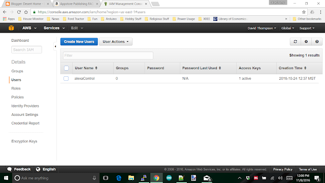
The very first thing you're going to need is a 'user'. To create a user that will be able to authenticate and use the various features, you use another Amazon Web Service IAM (Internet Access Management). This is where you'll poke in some permissions that will allow your Pi to assume the identity of the user you create and then upload temperature readings and such. At the AWS console, take a look around at the services and choose IAM and go there. Somewhere on that page is a button to create a user. These things move around on the screen depending on various criteria, so I can't tell you exactly where it will show up, but when I do it, it looks like this:


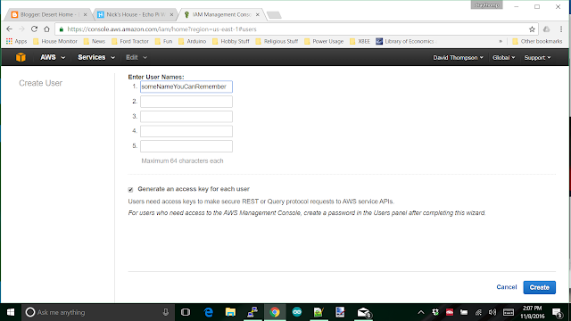
The 'alexaControl' user is the one I created to do things with. Create your own and you'll get a screen that looks something like this:


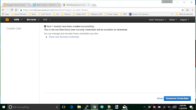
Hit the 'Create' button and you'll move to the next screen:


NOW, THIS IS IMPORTANT, click on the show credentials link. There is a secret shown that you won't be able to get again. You'll need both of the items in the next steps to create the thing. I took a screen shot so I wouldn't mess up entry of the items. I also did a copy and paste into notepad so I could copy them out. This is what they look like:


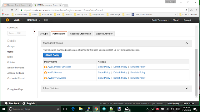
I didn't download the credentials.  Close the screen and you'll see your new user, click on it to get a screen where you'll assign various permissions and such. You don't need a 'group', but you do need to add some permissions. Click on the permissions tab and you'll get something like this:


Permissions in AWS are handled by 'policy' documents that are JSON files that are read when something needs to be done that may have to have a permission. Attach the three policies you see in the screen shot above. That gives pretty much unlimited permission to the stuff you're going to create. You can always come back later after it works and whittle down the permissions to what is actually needed, but it's much easier not to have to fight those items when you're first trying to get it working.

After you look around a bit at what the other items are, you can leave this part of AWS and, start looking for the AWS IOT console. We won't be using it yet, but it's good to have it up so you can check it after the next part.

I mentioned last post that I stepped through the creation of a thing using the web based tools that Amazon provides, but then I ran into trouble figuring out how to get the stuff I needed on my Pi so I could actually use it. That's where Nick's article came in handy. He has a step by step implementation of the items needed. Of course, I didn't do it exactly the same way he did, I used what I wanted to have. So, let's step through creating a thing and the various certificates we need on the Pi:

First, create a new directory somewhere and 'cd' into it; you'll be creating files there and you want to be able to find them later. Load the huge hunk of software that Amazon provides as an interface to your machine. I simply used the defaults and let it install:

sudo pip install awscli

This will load the python version of the AWS Command Line Interface that we'll be using. Next, you want to configure it, the command is:

$ aws configure

Which will prompt you for the security items I told you to save above. It will also ask you for the 'region'. THIS IS ALSO IMPORTANT, use 'us-east-1' for the region. AWS has data centers globally, and normally, you'd choose one close to you, but for Alexa, you must choose us-east-1 which may show up as N. Virginia in a few places on Amazon.

Now aren't you glad you listened to me and saved the secrets from above? Now the steps you run through on the Pi to get it ready to connect:

Create  a 'thing'

$ aws iot create-thing --thing-name "house"

I used the name 'house' for mine, yours could be anything you want.

Now you can list it and check that the command worked:

$ aws iot list-things
{
"things": [
  {
    "attributes": {},
    "thingName": "house"
  }
]
}

You'll need to use encryption, so create certificates and keys

$ aws iot create-keys-and-certificate --set-as-active \ 
--certificate-pem-outfile cert.pem \ 
--public-key-outfile publicKey.pem \ 
--private-key-outfile privkey.pem

This will have a lot of output to the screen, you can safely ignore it because it also creates files in the directory you're using that you will need later.

4. Get the certificate ARN which is the AWS Resource Name. You know you're in acronym hell when you're using acronyms made from acronyms. The ARN is going to be needed later, I highlighted it below:

$ aws iot list-certificates
{
"certificates": [
  {
      "certificateArn": "arn:aws:iot:us-east-1:926342229229:cert/58debbfe90fa58cad4df8426bdf3f20a71df7644437203e231b503b994dfb8f3",
      "status": "ACTIVE",
      "creationDate": 1467893789.688,
      "certificateId": "58debbfe90fa58cad4df8426bdf3f20a71cf7644437203e251b503b994dfb8f3"
  }
]
}

Word wrap kinda messed up the copy and paste above, but you get the idea. Download the root certificate from symantec. You'll need a root certificate and we get that from Symantec.com. If you want to know what a root certificate is and does, go look it up; the explanation is complex. To get it on the Pi:

$ wget https://www.symantec.com/content/en/us/enterprise/verisign/roots/VeriSign-Class%203-Public-Primary-Certification-Authority-G5.pem -O aws-iot-rootCA.crt

Now's a good time to discuss the certificates and keys you've accumulated. It's also a good time to round them up and keep them in a place you can remember and protect. Here's the list of my keys:

$ ls keys
aws-iot-rootCA.crt  cert.pem  privkey.pem  publicKey.pem

You should have all of them as well. I keep them in a directory called 'keys' and will soon limit access to them to the root user.

Now we need to create a policy that will allow your Pi to do things by giving it permission. You do this by creating a file that you will feed to aws and it will, in turn send it up to AWS on Amazon. The file contents:

{
    "Version": "2012-10-17",
    "Statement": [{
        "Effect": "Allow",
        "Action":["iot:*"],
        "Resource": ["*"]
    }]
}

Just use an editor, copy the stuff between the braces (include the braces at the beginning and end) and name the file something you'll recognize. The date in there is important, it's the version of software at Amazon that is used, don't change it. I followed Nick's suggestion and called it 'PubSubToAnyTopic', then use the file in the next command:

$ aws iot create-policy --policy-name "PubSubToAnyTopic" --policy-document file://iotpolicy.json

You'll get back:

{
    "policyName": "PubSubToAnyTopic",
    "policyArn": "arn:aws:iot:us-east-1:704749107060:policy/PubSubToAnyTopic",
    "policyDocument": "{\n    \"Version\": \"2012-10-17\", \n    \"Statement\": [{\n        \"Effect\": \"Allow\",\n        \"Action\":[\"iot:*\"],\n        \"Resource\": [\"*\"]\n    }]\n}",
    "policyVersionId": "1"
}

Attach the principal policy you just created, using the arn highlighted from earlier:

$ aws iot attach-principal-policy --principal "arn:aws:iot:us-east-1:926342229229:cert/58debbfe90fa58cad4df8426bdf3f20a71df7644437203e231b503b994dfb8f3" --policy-name "PubSubToAnyTopic"

Now, get the endpoint that you'll send data to. This is actually a URL that accepts mqtt data and gets it into Amazon. You will need the endpoint to actually send the data; it will show up in the code as the destination for data.

$ aws iot describe-endpoint

And you'll get back:

{
    "endpointAddress": "yournumberswillbehere.iot.us-east-1.amazonaws.com"
}

Now you have a place to send data to and a policy to handle the data. You created and named a 'thing' and it's ready to use.

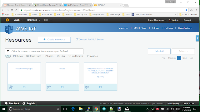
But, how the heck can you tell? Go to the AWS management console; you should be getting good with the names of things by now and sign in. Look at the black bar at the top, it should be 'N. Virginia' since we set up as 'us-east-1', but if it isn't use the selection and change it. Also up at the top in the black bar is 'Services' click on it and a huge drop down of services will show up. Choose 'AWS IoT and you should get a screen like this:


There's the policy, thing and endpoint that you created using the steps above. You can click on them and see stuff related to each of them. The thing is where your shadow document will be that you'll be working with going forward.

This posting has taken hours to put together and check over, so I'm going to write about sending data from the Pi up to the thing we just created next time. 

Amazon Dot, Sending Data From Raspberry Pi

$
0
0
Last post I showed you how to create a 'thing' and to get the necessary certificates and keys to enable communication from the Pi up to the Amazon AWS; now we need to look into sending some data up there. I tried the Amazon library that is supplied with the AWSIot, but frankly, it had a bug I couldn't tolerate as well as really pretty, but incomplete documentation. The bug is that you can't run two instances of it on a Pi. If you start up a second instance, the first one starts to fail, and I want to have more than one thing that can send data. The documentation only shows how to use it with Java and Javascript; the python descriptions are just not there. Also, each piece of it leaves things out that you need and I didn't want to spend even more hours experimenting.

The tutorials helped some, but like I said, not a one of them actually worked when I tried them, so I used Nick's example from my last post and built a process that could send data up, then I converted it to use simple mqtt calls and simplified it a whole lot. Nick's example can't receive data from Amazon, so that part had to wait until I got some experience.

To send data from your Pi up to Amazon is actually pretty simple, so let's step through some code to illustrate it. First, you have to have mqtt client installed. You don't actually need mqtt server unless you already use it for your stuff, so install mosquito. You can refer back to my post where I discovered how easy to use mqtt actually is for my instructions <link>, or use one of the hundreds of others out there. Once you've got it in place and tested a bit, you're ready to put something together that will send data up to Amazon AWSIot; yep, I'm going to use the acronyms; you should be used to them by now.

#!/usr/bin/python
import os
import sys
import time
import paho.mqtt.client as mqtt
import ssl
import json
import pprint
from houseutils import timer, checkTimer

pp = pprint.PrettyPrinter(indent=2)

def on_awsConnect(client, userdata, flags, rc):
    print("mqtt connection to AWSIoT returned result: " + str(rc) )
    # Subscribing in on_connect() means that if we lose the connection and
    # reconnect then subscriptions will be renewed. You still have to do the
    # reconnect in code because that doesn't happen automatically
    client.subscribe ([(awsShadowDelta , 1 ),
                      (awsShadowDocuments, 1)])
                      
# If you want to see the shadow documents to observe what is going on'
# uncomment the prints below.
def on_awsMessage(client, userdata, msg):
    #print "TOPIC = ",
    #print msg.topic
    #print "PAYLOAD = ",
    payload = {}
    payload = json.loads(msg.payload)
    #pp.pprint (payload)
    #print ""
         
    if msg.topic == awsShadowDocuments:
        print "got entire shadow document"
        #pp.pprint (reported)

    elif msg.topic == awsShadowDelta:
        print ("got a delta")
        #print (pp.pformat(payload["state"]))
            
def updateIotShadow():
    temperature = 79.1
    # Create report in JSON format; this should be an object, etc.
    # but for now, this will do.
    report = "{ \"state\" : { \"reported\": {"
    report += "\"temp\": \"%s\", " %(int(round(temperature)))
    report += "\"lastEntry\": \"isHere\"" #This entry is only to make it easier on me
    report += "} } }" 
    # Print something to show it's alive
    print report
    print("Tick")
    err = awsMqtt.publish(awsShadowUpdate,report)
    if err[0] != 0:
        print("got error {} on publish".format(err[0]))

if __name__ == "__main__":
    # these are the two aws subscriptions you need to operate with
    # the 'delta' is for changes that need to be taken care of
    # and the 'documents' is where the various states and such
    # are kept
    awsShadowUpdate = "$aws/things/house/shadow/update"
    awsShadowDelta = "$aws/things/house/shadow/update/delta"
    awsShadowDocuments = "$aws/things/house/shadow/update/documents"
    # create an aws mqtt client and set up the connect handlers
    awsMqtt = mqtt.Client()
    awsMqtt.on_connect = on_awsConnect
    awsMqtt.on_message = on_awsMessage
    # certificates, host and port to use
    awsHost = "data.iot.us-east-1.amazonaws.com"
    awsPort = 8883
    caPath = "/home/pi/src/house/keys/aws-iot-rootCA.crt"
    certPath = "/home/pi/src/house/keys/cert.pem"
    keyPath = "/home/pi/src/house/keys/privkey.pem"
    # now set up encryption and connect
    awsMqtt.tls_set(caPath, certfile=certPath, keyfile=keyPath, cert_reqs=ssl.CERT_REQUIRED, tls_version=ssl.PROTOCOL_TLSv1_2, ciphers=None)
    awsMqtt.connect(awsHost, awsPort, keepalive=60)
    print ("did the connect to AWSIoT")
    
    # Now that everything is ready start the mqtt loop
    awsMqtt.loop_start()
    print ("mqtt loop started")

    # this timer fires every so often to update the
    # Amazon alexa device shaddow; check 'seconds' below
    shadowUpdateTimer = timer(updateIotShadow, seconds=10)
    print("Alexa Handling started")

    # The main loop
    while True:
        # Wait a bit
        checkTimer.tick()
        time.sleep(0.5)

The code above is more than an illustration of what to do, it actually runs on my machine and will update the AWSIoT shadow I'm currently using. I took a lot out of it because you probably don't do the sensors the same way I do, and there's no point in showing how I read the sensor data out of the database and format it.

Let's start at the top and work our way down in the code. The first two routines, on_awsConnect() and on_awsMessage() are the mqtt callbacks that you'll use to connect, subscribe and publish to the AWSIoT mqtt server. In on_awsConnect() I subscribe to the general topic,

"$aws/things/house/shadow/update/documents"

and

"$aws/things/house/shadow/update/delta".

The 'documents' one is where you can see the entire shadow document and the 'delta' is where you derive the command sent to your code by Alexa. But, for now, we're only going to discuss the data we want to send up and that is published to the topic,

"$aws/things/house/shadow/update",

because that is the first thing you need to conquer in getting this running. I only illustrate the subscriptions here so you can get a feel for the message interaction.

Now, specifically in on_awsMessage() I publish to

"$aws/things/house/shadow/update",

a specific format that AWSIot expects, it actually looks like this,

{ "state" : { "reported":
   {
     "temp": "79",
     "lastEntry": "isHere"}
   }
}

if you remove all the "\" crap. I did it as a string (probably a mistake) to cut down on the time it was taking me to try things. The "lastEntry" was added by me to make it easier to add entries to the JSON string as I implemented different sensors. I just copied that line, pasted it back in and changed the stuff to be what I wanted to work on next.

Yes, it's just that simple to send an update message, the hard part was finding out what the format was and the specific mqtt topic to publish to.

Now, down in the main code there's a few declarations of the topics used to make it somewhat simpler to code, and then the objects for the mqtt client and callbacks. The next bit,

    awsHost = "data.iot.us-east-1.amazonaws.com"
    awsPort = 8883
    caPath = "/home/pi/src/house/keys/aws-iot-rootCA.crt"
    certPath = "/home/pi/src/house/keys/cert.pem"
    keyPath = "/home/pi/src/house/keys/privkey.pem"

are pretty much boiler plate for specifying the port you have to use, the actual server you send to and the fully qualified path names to your certificates. You got the certs from the previous example and should have saved them somewhere. The reason for the full path names is so this code can run in any directory. Port 8883 is the one chosen by Amazon, you can't change it. Then, 

    awsMqtt.tls_set(caPath, certfile=certPath, keyfile=keyPath, cert_reqs=ssl.CERT_REQUIRED, tls_version=ssl.PROTOCOL_TLSv1_2, ciphers=None)

    awsMqtt.connect(awsHost, awsPort, keepalive=60)

cause tls encryption to be implemented (this comes free with mosquitto client) and the actual connection to the server. Next,

    awsMqtt.loop_start()

you must have an mqtt loop of some kind so the queue can be read, and awsMqtt.loop_start() is non-blocking. This is important so you can control when the updates are sent to AWSIoT. The last little bit is using the simple timer I created to keep from starting a separate thread for timing something this simple. I used to use a much more complex timer set up, but that was a waste of resources. The timer code I used is described here <link>, but of course, you can do anything you want.

The way this code works is every so often (10 seconds in this example) the timer fires and calls updateIotShadow() which formats a message holding a temperature I just hard coded in, and sends it up to a specific topic on AWSIot using my credentials. This connects it to the right place and suddenly, I have the data available on Amazon. 

Yes, that's literally all there is to sending data and having it show up there. You can verify this by  going to the AWSIoT console and looking at your 'thing'; it will have an entry for 'temp' and a value of '79'. Now what you have to do is implement all your sensors in the message which will make you realize why I put the 'LastEntry' in there, and check it out in the console on Amazon.

So, now would be an excellent time to bookmark the Amazon AWSIoT console in your browser; you're going to be using it a lot. You'll also use bookmarks to the Amazon Lambda server, and the Alexa server a lot.

Next time, We're going to work on a Amazon Lambda function to receive requests from Alexa (I'll be using an Amazon Dot) and respond with the temperature we just sent up. It'll be in two parts because it's mildly complex and it's best to take this stuff on a bite at a time.

Have fun.


Amazon Dot Lambda function

$
0
0
Well, we've created a 'thing' and managed to send data from our Raspberry Pi over the internet to it and can see it in the AWSIoT console. Now we'll build a 'Lambda' funtion to interface between the shadow document and the Alexa voice service. The Lambda server is yet another cloud service offered by Amazon, and yet another, step in getting the data all the way back to us on the Amazon Dot. This is where we get to write some more code, this time in node.js.

I'm not going to teach you node.js; mostly because I don't know it all that well, and there are several thousand other sites that can help you with this part of the project. What I will do is show you the first bit of node.js code I put together for my project. This is another piece that is more than just an example; I ran this code for a couple of days getting my feet wet in handling this stuff.

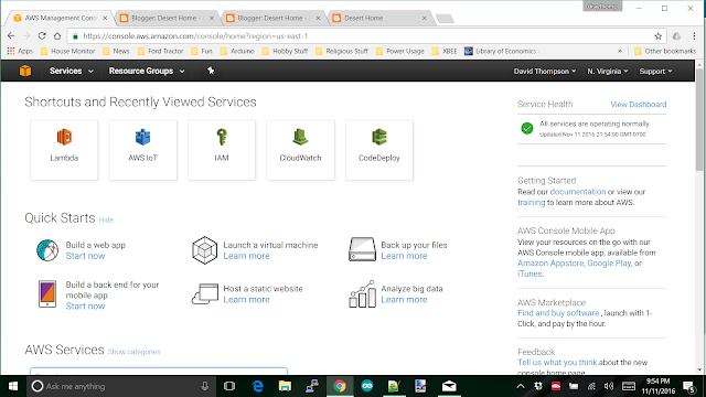
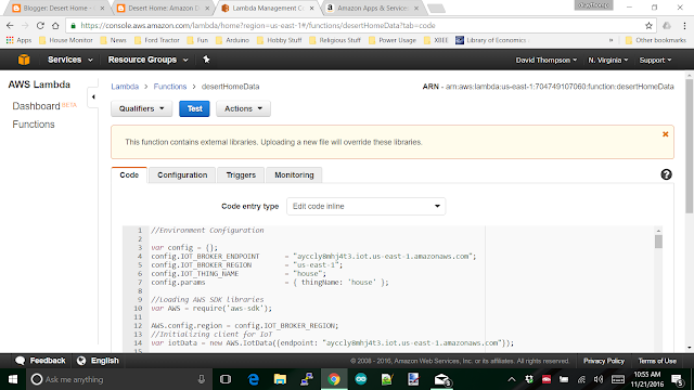
So ... login to the Amazon AWS console. Yes, you've been here before, and you'll be here several more times getting this working. I can't show you a picture of what it will look like for you since this is another one of those pages that change as you do stuff and get more bits of the project implemented. I can show you what it looks like for me:


Look around the screen and find 'Services', it's most likely up in the top black bar like this screen shows, and select it. You'll get the drop down menu of services and look for 'Lambda'. When you get to the next screen, you want to 'Create a Lambda Function'; it should be a big blue button. You be prompted to choose a blueprint for the function. You want to use Node.js 4.3 and you can filter on 'Alexa' to see what they offer for blueprints. I recommend just choose the 'Blank Function' from the menu and use the code I have placed below.

Now, since web postings hang around for years and years, look at the date of this post and remember that things have probably changed a lot since I wrote it and make an informed decision.

Anyway, the next screen wants you to configure a trigger. A trigger in this case is what will be calling your Lambda function, and you want Alexa to be the thing that activates the new function you're going to make. On the screen you'll see a rounded, dashed box beside the word 'Lambda', click there.


That will give you a drop down menu, choose 'Alexa Skills Set', NOT 'Alexa Smart Home'. 'Alexa Smart Home' is an even more complex interface to transfer data that was designed for businesses to implement their various smart devices into the AWS environment. I went that way at first and was driven to the brink of tossing the Dot back in the box and shipping it back to Amazon. I may go look at it again when my distaste subsides a bit, but that will take a while. I just couldn't get past the TON of requirements that seemed to crop up every time I tried to do something. Nope, just use the 'Skills' interface, you'll thank me later.

After you get that part done, click 'Next' and you'll get to the 'Configuration' screen. This is the place you'll do most of your work. When you get some code in and save it, you'll also get a 'Test' and other screens you can play with. For now, name your function and choose the runtime Node.js 4.3. You have other choices there including Python, but I couldn't find enough documentation on the python interface to do what needed to be done. There may be enough documentation in place when you get this far, but I gave up on finding it and just used Node.

A little lower on the screen you'll see a bit of code they supply as an example to get you started, replace that with the code I include below:

//Environment Configuration 

var config = {};
config.IOT_BROKER_ENDPOINT      = "yournumber.iot.us-east-1.amazonaws.com";
config.IOT_BROKER_REGION        = "us-east-1";
config.IOT_THING_NAME           = "house";
config.params                   = { thingName: 'house' };

//Loading AWS SDK libraries
var AWS = require('aws-sdk');

AWS.config.region = config.IOT_BROKER_REGION;
//Initializing client for IoT
var iotData = new AWS.IotData({endpoint: config.IOT_BROKER_ENDPOINT});

// Route the incoming request based on type (LaunchRequest, IntentRequest,
// etc.) The JSON body of the request is provided in the event parameter.
exports.handler = function (event, context) {
    try {
        console.log("event.session.application.applicationId=" + event.session.application.applicationId);

//        if (event.session.application.applicationId !== "amzn1.ask.skill.yoursecretnumbergoeshere") {
//             context.fail("Invalid Application ID");
        }

        if (event.session.new) {
            onSessionStarted({requestId: event.request.requestId}, event.session);
        }

        if (event.request.type === "LaunchRequest") {
            onLaunch(event.request,
                event.session,
                function callback(sessionAttributes, speechletResponse) {
                    context.succeed(buildResponse(sessionAttributes, speechletResponse));
                });
        } else if (event.request.type === "IntentRequest") {
            onIntent(event.request,
                event.session,
                function callback(sessionAttributes, speechletResponse) {
                    context.succeed(buildResponse(sessionAttributes, speechletResponse));
                });
        } else if (event.request.type === "SessionEndedRequest") {
            onSessionEnded(event.request, event.session);
            context.succeed();
        }
    } catch (e) {
        context.fail("Exception: " + e);
    }
};

/**
 * Called when the session starts.
 */

function onSessionStarted(sessionStartedRequest, session) {
    console.log("onSessionStarted requestId=" + sessionStartedRequest.requestId +", sessionId=" + session.sessionId);
}

/**
 * Called when the user launches the skill without specifying what they want.
 */
function onLaunch(launchRequest, session, callback) {
    console.log("onLaunch requestId=" + launchRequest.requestId + ", sessionId=" + session.sessionId);

    // Dispatch to your skill's launch.
    getWelcomeResponse(callback);
}

/**
 * Called when the user specifies an intent for this skill.
 */
function onIntent(intentRequest, session, callback) {
    console.log("onIntent requestId=" + intentRequest.requestId + ", sessionId=" + session.sessionId);

    var intent = intentRequest.intent,
        intentName = intentRequest.intent.name;

    //intent handling
    switch (intentName){
        case "GetTemperature":
            getTemperature(intent, session, callback);
            break;
        case "GetHumidity":
            getHumidity(intent, session, callback);
            break;
        case "AMAZON.HelpIntent":
            getHelp(callback);
            break;
        case "AMAZON.StopIntent":
        case "AMAZON.CancelIntent":
            handleSessionEndRequest(callback);
            break;
        default:
            throw "Invalid intent";
    }
}

/**
 * Called when the user ends the session.
 * Is not called when the skill returns shouldEndSession=true.
 */
function onSessionEnded(sessionEndedRequest, session) {
    console.log("onSessionEnded requestId=" + sessionEndedRequest.requestId +
        ", sessionId=" + session.sessionId);
    // Add cleanup logic here
}

// --------------- Functions that control the skill's behavior -----------------------

function getWelcomeResponse(callback) {
    var sessionAttributes = {};
    var cardTitle = "Welcome";
    var repromptText = "Are you there? What would you like to know?";
    var shouldEndSession = false;

    var speechOutput = "Desert home";
    callback(sessionAttributes, buildSpeechletResponse(cardTitle, speechOutput, repromptText, shouldEndSession));
}

function getHelp(callback) {
    var cardTitle = "Help";
    var repromptText = "Are you there? What would you like to know?";
    var shouldEndSession = false;

    var speechOutput = "Welcome to Desert Home," + 
        "dave is still working on what to say here,";
    callback(sessionAttributes, buildSpeechletResponse(cardTitle, speechOutput, repromptText, shouldEndSession));
}

function handleSessionEndRequest(callback) {
    var cardTitle = "Session Ended";
    var speechOutput = "Thank you";
    var shouldEndSession = true;
    callback({}, buildSpeechletResponse(cardTitle, speechOutput, null, shouldEndSession));
}

function getTemperature(intent, session, callback, sayit) {
    var cardTitle = "Temperature";
    var repromptText = "";
    var sessionAttributes = {};
    var shouldEndSession = false;
    var temp = 12;
    
   iotData.getThingShadow(config.params, function(err, data) {
       if (err)  {
           console.log(err, err.stack); // an error occurred
           temp = "an error";
        } else {
           //console.log(data.payload);           // successful response
           var payload = JSON.parse(data.payload);
           temp = payload.state.reported.temp;
         }

        speechOutput = "The temperature is " + temp + " degrees fahrenheit,";
        callback(sessionAttributes, buildSpeechletResponse(cardTitle, speechOutput, repromptText, shouldEndSession));
    });
}

function getHumidity(intent, session, callback) {
   var cardTitle = "Humidity";
   var repromptText = "";
   var sessionAttributes = {};
   var shouldEndSession = false;

   var humidity = 12;

   iotData.getThingShadow({ thingName: 'house' }, function(err, data) {
       if (err)  {
           console.log("error back from getThingShadow");
           console.log(err, err.stack); // an error occurred
           humidity = "an error";
        } else {
           //console.log(data.payload);           // successful response
           payload = JSON.parse(data.payload);
           humidity = payload.state.reported.humid;
         }

        speechOutput = "The humidity is " + humidity + " percent.";
        callback(sessionAttributes, buildSpeechletResponse(cardTitle, speechOutput, repromptText, shouldEndSession));
    });
}

// --------------- Helpers that build all of the responses -----------------------
function buildSpeechletResponse(title, output, repromptText, shouldEndSession) {
    return {
        outputSpeech: {
            type: "PlainText",
            text: output
        },
        card: {
            type: "Simple",
            title: title,
            content: output
        },
        reprompt: {
            outputSpeech: {
                type: "PlainText",
                text: repromptText
            }
        },
        shouldEndSession: shouldEndSession
    };
}

function buildResponse(sessionAttributes, speechletResponse) {
    return {
        version: "1.0",
        sessionAttributes: sessionAttributes,
        response: speechletResponse
    };
}

Nope, I'm not going to leave you in the dark; let's step through this code to see what the heck is going on. I won't cover every detail, but I promise to hit all the important parts.

It starts off with a boilerplate that you have to have to get various libraries and such into place and the first items you have to change are:

config.IOT_BROKER_ENDPOINT      = "yournumber.iot.us-east-1.amazonaws.com";
config.IOT_BROKER_REGION        = "us-east-1";
config.IOT_THING_NAME           = "house";
config.params                   = { thingName: 'house' };

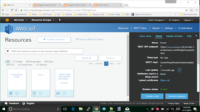
Broker endpoint is taken from AWSIoT which we dealt with in the previous posting <link>, and looks like this:


The number you want is in the upper right of the black section and you want only the portion after the 'https://' through the 'com'. Something like: yournumber.iot.us-east-1.amazonaws.com .  Broker_region must be "us-east-1", since that is the only endpoint that currently supports Alexa. Thing name is whatever you named your thing from my previous post, and the last bit is some JSON that will be needed later in the code; just replace 'house' with whatever you named your thing.

Moving on down you'll see the exports handler. This is the actual entry point into the Lambda function and is boilerplate, just use it until you get a feel for what is going on. Later, you may want to change it to do something special, but let's leave it alone for now. One thing I want to mention here is the two lines that are commented out:

//        if (event.session.application.applicationId !== "amzn1.ask.skill.yoursecretnumbergoeshere") {
//             context.fail("Invalid Application ID");

These lines stop the handler from going any further and return an error if the 'application-id' is wrong. There's the possibility that your function could get something intended for some other function and these two lines stop anything bad from happening in that case. However, we don't know what the appliation-id is yet, so comment this check out for now. The application-id can be read once it is working and put into the statement.

A little further down is onSessionStarted and onLaunch, they just log some stuff and Launch calls welcome, we'll talk about it in a bit. Then, you get to onIntent; this is where the work actually starts.

An 'Intent' is nothing more than an entry in a JSON string that is sent to the Lambda function. When I finally get to creating the voice interaction, you'll see that you create this intent which gets forwarded to the Lambda function. That's why the code is relatively simple to understand. This little bit of code illustrates it:

switch (intentName){
        case "GetTemperature":
            getTemperature(intent, session, callback);
            break;
        case "GetHumidity":
            getHumidity(intent, session, callback);
            break;

It's simply comparing the contents of one item in the JSON string sent to a string you defined in the voice interaction stuff that is coming later. In the example I started with there was a rather involved if-then-else construct here that I kept getting lost in, so I changed it to a switch statement so I could keep track of what was supposed to happen; feel free to rebuild it into whatever you want. I happen to like this.

The code that follows is where you get to gather the data from AWSIOT, compose a voice response and hand it back to be sent to the Dot. The fun stuff happens in this code, so to get an understanding of how to work with it, take a closer look at getTemperature().

function getTemperature(intent, session, callback, sayit) {
    var cardTitle = "Temperature";
    var repromptText = "";
    var sessionAttributes = {};
    var shouldEndSession = false;
    var temp = 12;

This is just basic variable set up for a little further down. I intentionally set the temperature to 12 so I could see it change when I get it from the shadow document.

   iotData.getThingShadow(config.params, function(err, data) {
       if (err)  {
           console.log(err, err.stack); // an error occurred
           temp = "an error";
        } else {
           //console.log(data.payload);           // successful response
           var payload = JSON.parse(data.payload);
           temp = payload.state.reported.temp;
         }

This uses one of their interface functions to get entire 'reported' section of the shadow document and parse out just the payload portion. If there's an error, it just sets the temp variable to 'an error', but with no error it gets the temperature you sent up. 

        speechOutput = "The temperature is " + temp + " degrees fahrenheit,";
        callback(sessionAttributes, buildSpeechletResponse(cardTitle, speechOutput, repromptText, shouldEndSession));

And here is where you tell the Dot what to say, and it's pretty obvious what I did here for the message. The 'callback' routine is how you give control back to Alexa and get out of the Lambda funtion.

I put the humidity function in so you could see how to handle more that one intent. It's the same as temperature. The last two routines handle stuffing your possible responses into a JSON message that is returned to the Alexa code; they make things easier for you and are part of the boilerplate.

And, there you have it, the horrifying Lamba function explained. Look up the page, save it, and we're ready to test it. First though, look at the page for the tabs, Configuration, Triggers and Monitoring. Triggers should already be filled in for you, but double check, it should look like this:


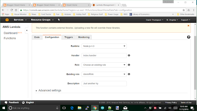
If it doesn't, you need to add in the Alexa Skills Kit as above. The Monitoring tab has cool graphs that are useless at this point. You may want to use them later, but wait until you get something working to play around in there. The Configuration tab needs to be checked, and there's a really important item in there that we have to attend to. First, here's what the screen looks like:


Double check runtime and handler. The one that will probably be messed up is role; you need to select an existing role, but the existing role doesn't exist yet. I fought this forever trying to get things to work. There were several examples out there on the web that showed something for this, but they were wrong. They were correct in how to set the role up, but not the actual permissions needed.

Open another window in the browser and go to AWS IAM, remember that from your previous work in defining the user? Once in the IAM console, select 'Roles' from the left hand side and you'll want to create a new role. Once again, a role is a JSON document that is read to allow permission to do things. You do not want to attach a policy, instead, create an inline policy. Here's the screen I get for this, but remember the screens change, look for similarities:


And, here is the JSON for the policy I came up with that finally worked:

{
"Version": "2012-10-17",
"Statement": [
{
"Effect": "Allow",
"Action": [
"iot:*",
"logs:CreateLogGroup",
"logs:CreateLogStream",
"logs:PutLogEvents"
],
"Resource": "arn:aws:logs:*:*:*"
},
{
"Effect": "Allow",
"Action": [
"iot:*"
],
"Resource": [
"*"
]
}
]
}
I had to add a separate section to the JSON to allow access to all resources for AWSIot. Most of the examples out there had this all shoved into one section and it just didn't work. Save your policy, give it a name you can remember and go back to the Lambda function and select the (now) existing role you just created. Yes, you may have to refresh the screen to have it read the new role, but you should be used that kind of thing.

Go back to the 'Code' tab and there should be a 'Test' button up at the top. You're not quite ready to test it because you have to create a test event to do anything. There are some examples of test events, but they don't cover enough possibilities to really do you much good. The best way to get a test event is to use the Alexa voice service to create one, but I haven't talked about that yet.

In the next post we'll visit that and create a tiny voice model that will call the lambda function. That will give you a test event that you can plug in and work with. Then you can expand on all of this to your heart's content.

Talk to you next time.

Amazon Dot, Let's Connect Alexa to the Lambda Function

$
0
0
Last Post <link> we did one more of the seemingly interminable steps to voice control in our house, the Lambda function, but we couldn't test it because we didn't have the proper input for it.  So, let's get into Alexa and create a voice service so we can actually start talking to it.

For those of you that jumped into the middle of this project, Alexa is the Amazon Voice Service that is the engine behind the Dot, Echo, that silly little switch they just came out with and probably more devices over time. It works pretty well and is actually pretty awesome for picking up voice in a house. I want it to control the items in the house with voice commands, and this is my latest attempt.

The really, really good news is that this is the last chunk of stuff we have to take on before we can get data from the house. We still have to work through the steps to send data, but all the major pieces will be there and we will get to just expand the capabilities.

So, sign into the Amazon Developer Console <link> and look up at the top black bar for 'Alexa' and click on it.


This is a tiny bit tricky because it looks like you want the 'Alexa Voice Service', but you really want the 'Alexa Skills Kit'. The voice service (in this case) is really meant for manufacturers to create interfaces for their devices. It's where folk like Belkin and Philips go to do things. If you have a hundred or so developers to work on this and relatively unlimited funds, by all means, go for it. If you're basically me, one guy trying to do something cool to have fun with, you definitely want the skills kit, so click on it.


This is what it looks like AFTER you create a skill, you want to 'Add a New Skill', which will take you to the next step:


Fill this in and click next. Remember, you want a 'Custom Interaction Model'. But, some advice on the 'Invocation Name', keep it short. Don't use something like, "Bill's really cool interface to the brown house at the corner," because you'll be saying this over, and over, and over. I used "Desert Home" and it's too darn long. 


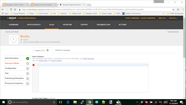
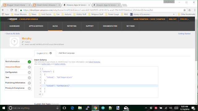
And here you are at the Interaction Model screen. Now you get to actually do some cool stuff. The top box is for a rather simple set of JSON (of course) strings, and the bottom is for 'utterance' that will use those JSON strings to create requests that will be spoon fed to the Lambda function we just created. Here's the intents for the Lambda function we created previously:


It's a JSON string with a table of  'intent' entries. Now we want to scroll down a bit to put in some utterances:


And 'Save' them. The save function will actually create the model which means you may get an error. So far, the errors I've had were relatively self-explanatory. Things like misspelling a word or forgetting a comma. Each of the lines of  the utterances start off with one of the intents you defined in the first box and the rest of it are regular words that you speak to the Dot. The more of these utterance you put in, the smoother it seems to work when you use it. For now, just put a few in, you can add to them later as you see fit. When you get it saved; I mean really saved, and see the message above, click 'Next'.


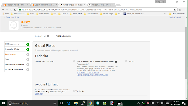
The 'Service Endpoint Type' is AWS Lambda of course because we went to all the trouble of creating a Lambda function for it, and you do not want users to link their accounts to this. Linking accounts is for selling services through Amazon. When you click on the Lamba radio button, it will open a couple of items you have to fill in:


Since Alexa only works in North America that button is obvious, the empty field is something to drive you nuts. Notice they don't give you a hint what they want in here? No help button, ... NOTHING!

What they want is the arn (Amazon resource number) of the Lambda we created last post, so go there and get it. Copy it out and paste it in here. I put mine in there so you could see what it looks like. Now, click 'Next'


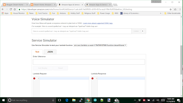
You're on the TEST SCREEN !! Finally, you get to do something and see something happen. Sure, we saw a little bit happen way back when we were messing with the mqtt interface to the AWSIot, but that was way back there. This time we get to actually try some voice related stuff. Whoo Hoo.

Just ignore the silly blue message about completing the interaction model. That message seems to always be there; click the enable button and watch the glorious test screen expand:


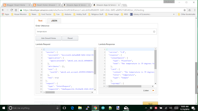
You get a voice simulator where you can type stuff in and have Alexa speak it back to you. There's a service simulator where you can type in text and Alexa will shape it into a JSON string that will be sent to the Lambda function, which will do whatever you told it to do and send back a response (or error) that you see in the other window. If it works, there's a button down the screen that will allow you to play the text from the response. Here's what one interaction (that actually worked) looks like:


The Lambda request window is where you can copy the JSON to use in testing the Lambda function directly, you just configure a test, copy that stuff in and go for it. 

You DON'T want to publish this. If you publish it, you'll be allowing whoever hooks their Dot or Echo to this skill to mess with your house. It'll work just fine with your Dot, go give it a try once you work out whatever kinks that might have kicked in.

So, now we can get the temperature from our house by voice. Next we want to actually control something. That will mean changes to the voice model, the Lambda function and the code on our Pi.

Bet you can't wait for the next installment where I'm going to discuss a little bit about debugging the Lambda function and start down the path to changing something using voice commands to the house. 

Have fun.

Amazon Dot: Let's Turn Something On

$
0
0
Last post <link> we got data all the way from a Raspberry Pi up to Amazon and back to the Dot and it was able to say,  "The temperature is 79 degrees, " and we were excited. What, you got an error? How the heck do you troubleshoot this thing?

Fortunately, there actually is a way of doing this, even with the fact that they pass complex JSON strings around to carry data from one subsystem to another. The screen you got last time:


has the json string you need to test directly into the Lamba function we created in a previous post <link>. Simply copy the entire 'Lambda Request' and then paste it into the test screen for the Lambda function. I know this description leaves a lot of questions, so let's look a bit closer:

First copy the entire text from the Lambda Request shown above, then go to the Lambda Management Console:


Then select Actions -> Configure Test Event


They don't have a blank test event or something really close to what you need, so just chooses the first one 'GetNextFact' and replace ALL the text inside the edit box with what you saved above. This will replace the default with what you want. Save it; you have to scroll down on the page to get the save button to show.

Now, you're ready to actually feed the JSON to your Lambda function. You can now press the 'Test' button and see what happens. I can't really be much help on specific errors because I can't know in advance what kinds of problems you'll hit, but there should be enough information to get you started.

You can also edit the test event you just created to test other things, I used one test event to test most of my information requests; things like 'temperature', 'rainfall', by just changing the intent name inside the JSON string.

Now you have some hope of being able to debug this thing, so let's walk through adding control of something from the Dot. This time I'm going to start with the voice interaction and work down to the Raspberry Pi at my house instead of the other way around. The reason for doing it this way is because we now have the basic infrastructure in place and adding things is easier from the Dot back to the Pi. We'll start at the Alexa Interaction Model which looks like this:


There needs to be an intent added and I'm using the one I added first to my setup. The intent is ControlEastPatioLight and it has two 'slots', on and off, so I named the type onOff. Very clever of me. Just below the intent window, I added a new slot called (duh) onOff:


And the contents of the slot is:


What's happening is that Alexa doesn't send the actual text that is spoken, it sends intents which may contain enumerations to the Lambda function. Enumerations are simply things that can be chosen from a pre-defined list. In this case the two slot values I chose were 'on' and 'off'. I could have used 0 and 1, or Fred and Mary, it doesn't matter what they are, what matters is that they make sense to you because you have to use them later in actually controlling your devices.

Now, for the utterances, I used the simplest ones I could think of:


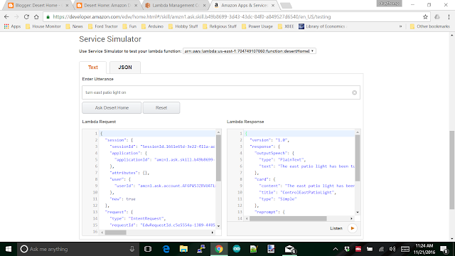
I highlighted the two above that I use for the light. The '{state}' refers back to the intent I created above and will be replaced with either on or off from the slot definition based on what you actually say to the Dot. Alexa actually parses through the sound and inserts its best guess about you said into the JSON string that will be sent to the Lambda function. So, save this work and go test it in the test screen:


Your Lambda Response will be an error because you haven't added the code yet, but the test generated the Lambda Request you'll need to test the new capability you're adding, so copy it out of the Request window and go over to the Lambda function and paste it into the test configuration before it gets lost:


It's not ready to test yet since we don't have any code to support it, but save it now for uses later. We're going to add code now to support the new intent. In the code window which you will see after you save the  event template you want to add the code. The window is small and hard to use, but you can scroll all the way down to the bottom of the little code window and there will be a button to expand it to full screen, I use this to edit since there just isn't enough visible to get proper context for changes:


The button is in the image above over on the right; I put the cursor there so you could find it. I searched for this for about 20 minutes the first time.

Add a couple of lines into the intent handling to get you to a routine that will format the mqtt request that the AWSIoT needs:


I highlighted the lines in the picture above. Now you need the code to create the mqtt request:


It just barely fit on the screen. Since you've already done this once, it should be easily recognized with the difference being the payload object and a call to updateThingShadow(). I think it's pretty intuitive what is going on here. A JSON fragment string is created with the content of the slot created above and passed off to the shadow as a 'desired' item. Now you're starting to understand why I described the operation of a 'Device Shadow' so carefully back a few posts ago <link>; the interaction of the shadow and the code on the Raspberry Pi is very important to getting this stuff working.  I know how big a pain in the bottom it is to read from a post and try to type it in, so here's the code above you can copy and paste with:

function controlEastPatioLight (intent, session, callback) {
    var repromptText = null;
    var sessionAttributes = {};
    var shouldEndSession = false;
    var speechOutput = "";
    var newstate = intent.slots.state.value;

    //Set the light to 0 to turn it off
    var payloadObj={ "state":
                        { "desired":
                            {"eastPatioLight":newstate}
                        }
                 };
    //Prepare the parameters of the update call
    var paramsUpdate = {
        "thingName" : config.IOT_THING_NAME,
        "payload" : JSON.stringify(payloadObj)
    };

    //Update Device Shadow
    iotData.updateThingShadow(paramsUpdate, function(err, data) {
        if (err){
           console.log(err, err.stack); // an error occurred
        }
        else {
            speechOutput = "The east patio light has been turned " + newstate + "!";
            console.log(data);
            callback(sessionAttributes,buildSpeechletResponse(intent.name, speechOutput, repromptText, shouldEndSession));
        }    
    });
}


Be sure to change the various names to something you'll understand later.

Once again, we don't actually send a command to the Pi to change something, we send a desire. That desire is pulled off the mqtt queue and used to do the actual change, then we publish back the new state. But, if you get confused, go back and read the explanation I linked to in the last paragraph.

That's it for right now, the next post has a bunch of code in it for the raspberry pi to get the desire and do something about it. It's going to get confusing to both read and for me to write, so next post.

Have fun, and feel free to work ahead, you can actually see the desire created and sent over in AWSIot if you want to.

Amazon Dot: Now for the code on the Raspberry Pi

$
0
0
Last post <link> I stepped through creating the voice model and the Lambda function in Amazon Web Services (AWS) that got my request to manipulate the light on my East patio light out to Amazon's mqtt server for this service that they call, AWSIot (Amazon Web Services Internet of Things). Yes, it's a big name for something like this, but how else are you going to sell it? Gotta have a lot of marketing hype to impress the Harvard School of Business Managment.

At any rate, it's a good implementation of mqtt that reacts pretty quickly and will send the mqtt message containing the data I need to control the light. When you do this, you'll need something on the Pi to receive the message and do something with something real.

Unfortunately, I can't do that part for you.

I can show you how to receive the message and take it apart, but the actual twiddling of bits, or however you control your devices is up to you. I use a mix of XBees and web based devices and they certainly won't fit in with what you do. So, I'm going to use a couple of variables and just change them. You can take that and run with it since we all have variables.

Let's do this with code I put together special for just this purpose. In the code I initialize the variable to something so I can tell they changed, get and respond to the messages from Amazon that were initiated by voice command to the Dot, then change the values based on that. I'll build on the example I provided previously to get the temperature at my house, so if you don't remember what I did there (I wouldn't) go back a glance at it for a minute <link>; I'll wait.

Here's the python code:

#!/usr/bin/python
import os
import sys
import time
import paho.mqtt.client as mqtt
import ssl
import json
import pprint
from houseutils import timer, checkTimer

pp = pprint.PrettyPrinter(indent=2)

def on_awsConnect(client, userdata, flags, rc):
    print("mqtt connection to AWSIoT returned result: " + str(rc) )
    # Subscribing in on_connect() means that if we lose the connection and
    # reconnect then subscriptions will be renewed. You still have to do the
    # reconnect in code because that doesn't happen automatically
    client.subscribe ([(awsShadowDelta , 1 ),
                      (awsShadowDocuments, 1)])
                      
def on_awsMessage(client, userdata, msg):
    global eastPatioLight
    
    # If you want to see the shadow documents to observe what is going on
    # uncomment the prints below.
    #print "TOPIC = ",
    #print msg.topic
    #print "PAYLOAD = ",
    payload = {}
    payload = json.loads(msg.payload)
    #pp.pprint (payload)
    #print ""
    
    # The 'delta' message is the difference between the 'desired' entry and
    # the 'reported' entry. It's the way of telling me what needs to be changed
    # because I told alexa to do something. What I tell alexa to do goes into
    # the desired entry and the delta is then created and published. Note that
    # the delta is not removed, it has to be done specifically, hence the 
    # code further down.
    
    if msg.topic == awsShadowDelta:
        print "got a delta"
        pp.pprint(payload["state"])
        for item in payload["state"].keys():
            if item == "eastPatioLight":
                command = str(payload["state"][item])
                print "got command for east patio light: ", command
                # This is where you would actually do something to
                # change the state of a device.
                eastPatioLight = command
            else:
                print("I don't know about item ", item)
                
    # Right under here I get the entire document and compare the 'desire' part
    # to the corresponding items in the 'reported' part. When I find something in
    # the desire that is the same as something in the reported, I remove the entry
    # from the desire. If you get rid of all the entries in desire, the entire
    # desire part of the document is removed and just disappears until it's 
    # needed later.
    
    # The reason for this is because when the desire stays around and you walk
    # over and change something by hand, AWS will generate a delta because the
    # reported is suddenly different from the desired. That means you open the
    # garage door by hand, aws senses that the desire is closed, sends a delta
    # and closes the garage door on you.
    
    # Fortunately, I discovered this with a light, not a garage door.
        
    elif msg.topic == awsShadowDocuments:
        #print "got full thing"
        
        # AWSIoT sends the 'reported' state back to you so you can
        # do something with it if you need to. I don't need to deal 
        # with it ... yet.
        if "desired" not in payload["current"]["state"]:
            #print "'desired' not there"
            return
        desired = payload["current"]["state"]["desired"]
        reported = payload["current"]["state"]["reported"]
        #pp.pprint (reported)
        
        # This is probably a left over 'desired' state, which means
        # you've already changed something, but the desire is still
        # left hanging around, so compare it with the reported state
        # and if it has been satisfied, remove the desire from AWSIoT
        pp.pprint (desired)
        fixit = False
        fixitString = "{ \"state\" : { \"desired\": {"
        for item in desired.keys():
            # when updating this, you'll often encounter
            # items that aren't fully implemented yet
            # (because you're still working on them)
            # this not reported it's just to keep from dying
            if not reported.get(item):
                print ("found odd item " + item)
                break
            if desired[item] == reported[item]:
                fixit = True
                print "found left over desire at", item
                # to get rid of a desire, set it to null
                fixitString += "\"" + item + "\": null,"
        if not fixit:
            return
        fixitString = fixitString[:-1] #remove the trailing comma JSON doesn't like it
        fixitString +="} } }"
        print "sending:", fixitString
        err = awsMqtt.publish("$aws/things/house/shadow/update",fixitString)
        if err[0] != 0:
            print("got error {} on publish".format(err[0]))
    else:
        print "I don't have a clue how I got here"

# This keeps the Shadow updated with the latest state of the devices
# If you go over and push a button to turn on a light, you want the shadow
# to know so everything can work properly.        
def updateIotShadow():
    global temperature 
    global barometer
    global eastPatioLight
    print "Variable states: ", temperature, barometer, eastPatioLight
    # Create report in JSON format; this should be an object, etc.
    # but for now, this will do.
    report = "{ \"state\" : { \"reported\": {"
    report += "\"temp\": \"%s\", " %(int(round(temperature)))
    report += "\"barometer\": \"%s\", " %(int(round(barometer)))
    report += "\"eastPatioLight\": \"%s\", " %(eastPatioLight.lower())
    report += "\"lastEntry\": \"isHere\"" #This entry is only to make it easier on me
    report += "} } }" 
    # Print something to show it's alive
    print "On Tick: ", report
    err = awsMqtt.publish(awsShadowUpdate,report)
    if err[0] != 0:
        print("got error {} on publish".format(err[0]))

# These are the three items we'll deal with in this example
# They represent real devices that measure or change something
# that have been implemented somewhere.
temperature = 79.1
barometer = 1234.5
eastPatioLight = "on"

def updateWeather():
    global temperature
    global barometer
    # if you had a real device, this is where you read its status
    # and update the variables so the values would be reported back
    # to AWSIoT
    temperature = temperature;
    barometer = barometer;

# Actually starts here      
if __name__ == "__main__":
    # these are the two aws subscriptions you need to operate with
    # the 'delta' is for changes that need to be taken care of
    # and the 'documents' is where the various states and such
    # are kept
    awsShadowDelta = "$aws/things/house/shadow/update/delta"
    awsShadowDocuments = "$aws/things/house/shadow/update/documents"
    # this is the mqtt resource that you respond to when you change 
    # something.
    awsShadowUpdate = "$aws/things/house/shadow/update"
    # create an aws mqtt client and set up the connect handlers
    awsMqtt = mqtt.Client()
    awsMqtt.on_connect = on_awsConnect
    awsMqtt.on_message = on_awsMessage
    # certificates, host and port to use
    awsHost = "data.iot.us-east-1.amazonaws.com"
    awsPort = 8883
    caPath = "/home/pi/src/house/keys/aws-iot-rootCA.crt"
    certPath = "/home/pi/src/house/keys/cert.pem"
    keyPath = "/home/pi/src/house/keys/privkey.pem"
    # now set up encryption and connect
    awsMqtt.tls_set(caPath, certfile=certPath, keyfile=keyPath, cert_reqs=ssl.CERT_REQUIRED, tls_version=ssl.PROTOCOL_TLSv1_2, ciphers=None)
    awsMqtt.connect(awsHost, awsPort, keepalive=60)
    print ("did the connect to AWSIoT")
    
    # Now that everything is ready start the mqtt loop
    awsMqtt.loop_start()
    print ("mqtt loop started")

    # this timer fires every so often to update the
    # Amazon alexa device shadow; check 'seconds' below
    shadowUpdateTimer = timer(updateIotShadow, seconds=10)
    weatherUpdate = timer(updateWeather, seconds=3)
    print("Alexa Handling started")

    # The main loop
    while True:
        # Wait a bit
        checkTimer.tick()
        time.sleep(0.5)

Now, as usual, I'm going to step you through it so you have a chance of understanding what is going on. You'll have to adapt this to your devices and it's best if you understand it instead of copy and paste.

So, let's go to the bottom of the code where it says "Actually starts here," and see how to set things up. I start off with creating a couple of variables that hold the subscriptions that will be used. These will certainly be different from yours, so put your own device name in here where mine says 'house'. Then I create another one for the mqtt topic that we will be responding to. Same thing, change it to match yours.

Take special note here that this is a regular old mqtt client implementation, I DID NOT use their special library because of problems I encountered with it.

The next hunk of code we've seen and gone through the explanation already when we set up to send sensor data up to AWSIot, so I'm not going to repeat myself here <link>. Down at the line where I talk about timers, you'll see two of them; one is for updating the Shadow and the other is for updating the variables that I'm using to simulate real sensor devices. That code is so you can slip in whatever code you need to get the values and save them for updating AWSIoT. I do a lot of stuff with timers since it allows other processes to get time to run. That way I leverage all the power I can out of a little Raspberry Pi.

Below that, I just sleep for a half-second and update my timer and go back to sleep. Every 3 seconds I update the sensor variables and every 10 seconds I update AWSIot. Those numbers seem to work reasonably well for a demo, but you may want to play with them in your particular situation.

So, now that I'm hung up in a loop waiting for events (timers and such), I'll get a call to on_awsConnect() that is the result of the awsMqtt.connect() call I did a little up the page. The handler awsConnect() is up at the top of the file and that's where we'll subscribe to the two mqtt topics we need to listen to:

client.subscribe ([(awsShadowDelta , 1 ),
                      (awsShadowDocuments, 1)])

The Delta one is where commands come from and the Documents is where you get a report on the actual contents of the Shadow; we'll use both of them in this. 

Once we have subscribed, the timer will expire for updating the Shadow and we'll compose a JSON message to AWSIot that holds the state of the items we're reporting. This is done in the routine updateIotShadow() and covered in the other post I mentioned (twice now) and is sent to the 'update' topic:

 err = awsMqtt.publish(awsShadowUpdate,report)
 if err[0] != 0:
     print("got error {} on publish".format(err[0]))

And, the shadow now contains the latest information for Alexa to grab and report back to you through the Dot. Notice that I added the patio light in there.

Now we get to the good part, tell the Dot to turn on the east patio light and the voice service will compose an intent, and send it to the Lambda function which will format a 'desire' into the Shadow document. AWSIot will look at this desire and notice that it's different from what the Shadow currently is and create a 'delta'. Remember that all this is just JSON text inside the Shadow document, there's nothing magical going on.

The 'delta' portion of the JSON is sent to the mqtt topic I stuffed in the variable awsShadowDelta and the Pi code will be called at on_awsMessage() and handed the message. The code in the message handler is totally new, so let's step through it a bit closer.

    # If you want to see the shadow documents to observe what is going on
    # uncomment the prints below.
    #print "TOPIC = ",
    #print msg.topic
    #print "PAYLOAD = ",
    payload = {}
    payload = json.loads(msg.payload)
    #pp.pprint (payload)
    #print ""

Like it says, there's the opportunity to get further debugging as you need it here, but all this basically does is get the contents of the delta into a variable called 'payload'.

    if msg.topic == awsShadowDelta:
        print "got a delta"
        pp.pprint(payload["state"])
        for item in payload["state"].keys():
            if item == "eastPatioLight":
                command = str(payload["state"][item])
                print "got command for east patio light: ", command
                # This is where you would actually do something to
                # change the state of a device.
                eastPatioLight = command
            else:
                print("I don't know about item ", item)

I look at the mqtt topic and see if it's a delta message, print it so you can see what you got and then step through each (there can be more than one) item and change that came in. I index into payload and grab the command for eastPatioLight and set the variable to whatever came in. Seems simple right? Frankly, this was a real pain to figure out, but I finally got there.

That's it for handling the delta and turning on the patio light, but there's a ton of code just below that handles cleaning up after the command has been processed. What's going on is that the delta message keeps coming until it has been removed. This makes perfect sense when you consider that something may happen to the original message and it may need to be resent to accomplish whatever is needed. However, it does need to be taken care of.

What I do here is get the delta from a different mqtt subscription I called awsShadowDocuments which has all three sections in it. It has the desire, reported and delta all in one neat package. So, I just get the desired entry, look for it in the reported JSON and remove it if it's already been reported back in the correct state.

    elif msg.topic == awsShadowDocuments:
        #print "got full thing"
        
        # AWSIoT sends the 'reported' state back to you so you can
        # do something with it if you need to. With the exception of
        # this code, I don't need to deal with it ... yet.
        if "desired" not in payload["current"]["state"]:
            #print "'desired' not there"
            return
        desired = payload["current"]["state"]["desired"]
        reported = payload["current"]["state"]["reported"]
        #pp.pprint (reported)
        
        # This is probably a left over 'desired' state, which means
        # you've already changed something, but the desire is still
        # left hanging around, so compare it with the reported state
        # and if it has been satisfied, remove the desire from AWSIoT
        pp.pprint (desired)
        fixit = False
        fixitString = "{ \"state\" : { \"desired\": {"
        for item in desired.keys():
            # when updating this, you'll often encounter
            # items that aren't fully implemented yet
            # (because you're still working on them)
            # this not reported it's just to keep from dying
            if not reported.get(item):
                print ("found odd item " + item)
                break
            if desired[item] == reported[item]:
                fixit = True
                print "found left over desire at", item
                # to get rid of a desire, set it to null
                fixitString += "\"" + item + "\": null,"
        if not fixit:
            return
        fixitString = fixitString[:-1] #remove the trailing comma JSON doesn't like it
        fixitString +="} } }"
        print "sending:", fixitString
        err = awsMqtt.publish("$aws/things/house/shadow/update",fixitString)
        if err[0] != 0:
            print("got error {} on publish".format(err[0]))


Pay special attention to the above where I iterated through the desire JSON because there may be more than one thing in there; especially if you've been testing various items. And, of course, there's the usual catch all else statement:

    else:
        print "I don't have a clue how I got here"

And, that's it. We've covered the entire code that runs on the Pi to catch requests sent by the Lambda function created in the last post. Cool.

Also, we've actually stepped through a full build of the voice system. You can now actually control something in your house using voice; way better than a 'Clapper' (if you don't know, google it).

This is the last post where I'll work through the various topics, I'm going to put together an Errata post where I'll list some of the gotchas that can creep up and get you, but that may be a while. Also, understand something, you can't just say, "Turn on East patio light," it doesn't work that way. Using the code and methods I presented you have two methods of controlling things. For example:

Alexa (wait for it to hear you and wake up)
ask (or tell) desert home turn on east patio light
(it will respond back whatever you put in the Lambda function)

or

Alexa (wait for it to hear you and wake up)
Desert home (wait for it to respond with text from your Lambda function)
east patio light on

The first will get you there in one sentence, the other takes two, but is more fun. Due to the way I coded it, both will keep the session open for 10 seconds so you can do another command. I generally check the temperature and something else in one session, then tell it to "stop". Yes, I have code in there to handle the "stop" command.

Yes, you DO have to say both Alexa and your thing name (desert home in my case); this isn't Star Trek yet. However, once you get in session you can say a command over and over as long as you don't wait 10 seconds and the automatic session tear down happens. So:

Alexa
Desert home (wait for response)
East patio light on (wait for response)
What is the temperature? (wait)
What is the windspeed? (wait)
Turn off outside lights (wait)
etc.

The automatic session tear down is 10 seconds and can't be changed. Otherwise, someone out there would set it for hours eating up Amazon resources.

Another thing, remember back a bunch of postings ago where I told you that they change the interface often and without warning? Well during the period of putting together these posts they implemented an entirely new interface for AWSIoT and I had to prowl around it for about thirty minutes to get any information about what was going on with my implementation. You'll probably have to prowl a bit also.

Like I said, there hundreds of them spread around the world and only one of me out here in the desert.

Sigh.

Yet another post (I forgot something) <link>

Amazon Dot: Oops, Forgot Something

$
0
0
Just when I thought I could put this series of posts on the Amazon Dot and using it at my house aside for a while, I realized I forgot something last time <link>. I didn't show what a session with the example code I gave you last time looked like and what it was doing. So:

pi@housemonitor:~/src/alexa$ alexaIllustration.py
did the connect to AWSIoT
mqtt loop started
Alexa Handling started
mqtt connection to AWSIoT returned result: 0
Variable states:  79.1 1234.5 on
On Tick:  { "state" : { "reported": {"temp": "79", "barometer": "1235", "eastPatioLight": "on", "lastEntry": "isHere" } } }
Variable states:  79.1 1234.5 on
On Tick:  { "state" : { "reported": {"temp": "79", "barometer": "1235", "eastPatioLight": "on", "lastEntry": "isHere" } } }
{ u'eastPatioLight': u'off'}
got a delta
{ u'eastPatioLight': u'off'}
got command for east patio light:  off
Variable states:  79.1 1234.5 off
On Tick:  { "state" : { "reported": {"temp": "79", "barometer": "1235", "eastPatioLight": "off", "lastEntry": "isHere" } } }
{ u'eastPatioLight': u'off'}
found left over desire at eastPatioLight
sending: { "state" : { "desired": {"eastPatioLight": null} } }
Variable states:  79.1 1234.5 off
On Tick:  { "state" : { "reported": {"temp": "79", "barometer": "1235", "eastPatioLight": "off", "lastEntry": "isHere" } } }


Above is a session where I start the process and give it a command. The first thing that happens is that a connection to AWSIot is established. This is really a normal ol' mqtt connect, and then an mqtt loop is started. This is an asynchronous loop that will return control back to the code so other things can be done.

When the connection calls back the code subscribes to the two topics and prints the connection message, "mqtt connection to AWSIoT returned result: 0." This means that we are all set up and ready to receive messages from Amazon. I printed the starting state of the variables next and the interesting one is the eastPatioLight which I initialized to 'on'.

The 'On Tick' messages are the reports we're sending up to Amazon. I have this set up for every ten seconds so we don't have to wait long to see something. Scan down a bit and look for, "got a delta," because that is the point where a command came in from Amazon. In this case it's a command to turn the eastPatioLight off.

The next 'On Tick' message says that the light is now 'off' and should change the Shadow document to reflect that. Then, the code sees another delta message and checks to see if it has already been satisfied and decides that it's simply a leftover desire and sends back a JSON string:

{ "desired": {"eastPatioLight": null} } }

This will remove the desired entry from the Shadow and therefore, the delta message will stop.

And it's done. The variable has been changed to 'off' and if you had code there to turn off your lights, so would be the light.

After you work with the interaction a bit, it will all make sense and will be MUCH easier to modify for your particular use and add stuff to.

Have fun.

Adventures With My Freezer (the one in the house)

$
0
0
Over the years I've been doing modifications to the freezer in my kitchen. It all started way back in 2014 when I decided to not only measure the power usage of this device <link>, but to also control when the defroster runs <link>.

A tiny bit of background for folk that haven't been following my silliness for very long: I'm trying to lower my electricity bills here in the Arizona desert, and have a power company that offers a lower rate during off hours. What I do is try to keep all my major usage in the non-peak hours, and having the defroster run whenever it wants to sometimes leads to defrosting in the middle of the peak period. Also, I bought this freezer because it is simple, really simple. There's no huge electronic package in there that is designed to save power, hook to the internet, take pictures, call my Mom, etc. It's just the basic freezer, albeit a high capability, and repairable model that looks really good.

I also added the ability to monitor the temperature inside the freezer <link> after my 'wonderful' defrost controller crapped out. While I was fixing that I decided to combine the two relays on the Arduino shield I was using to parallel the contacts, hoping to extend the life of the relays.

Don't ever do that !!

I totally forgot that doubling the number of components also doubles the possibility of failure, as well as doubling the ways they can fail. This is a great story of doing the wrong thing, so I'm going to teach you a bit about the defrost cycle on a freezer so you understand what I got myself into. Since I have the ability to chart the actual action of my freezer, you get to have real examples of my (seemingly infinite) ability to screw up.

This is what a normal defrost cycle looks like when you can observe both temperature and power usage.


Ignore point A, that's the icemaker running to dump ice in the tray, and the tiny bump next to it is the lights in there when I open the door.

Point B is the start of the defrost cycle, this happens on a timer that closed a SPDT set of contacts that shuts off the compressor and kicks on a heater that is actually attached to the evaporator at the bottom of my fridge.

Point C is where the heater is running, and it will run until a temperature sensor (also mounted on the evaporator) reaches a built-in temperature that the manufacturer thinks is the best to clear the frost away. In my particular case this thermostat is 37F.

Point D is where the heater shut off and the freezer just sits there until the timer runs out after 30 minutes. This is to allow the water to drain out the bottom into an evaporation tray and away from the freezing area of the freezer.

Point E is where the compressor kicks back on, the spike is the usual one you get from the run capacitor letting a lot of power through to get things going.

Point F is the normal compressor run cycle. It runs until the Freezer gets to operating temperature and then shuts off. On freezers the compressor runs a long time, but that's OK because these things only use around 100W. In the days before LED lights in appliances, the lights used a lot more power than the compressor did.

So, the heater pulls around 400W, but should only run for around 15 minutes, however once in a while it because of high local humidity, someone holding the door open too long, trying to freeze a gallon of hot water, or something like that, the heater will run the entire 30 minute cycle time. When this happens, the next defrost cycle will take care of the left over buildup.

Unless something is broken, or you've got someone in the house that messed things up.

I noticed that the temperature in my freezer was gradually rising and the compressor seemed to be running too long. Here's a chart of what I saw when I looked at it:


Once again, the sharp peaks are the icemaker doing its thing, but let me step through the other parts I pointed out:

A is where the compressor started. This part appears perfectly normal.

B is where the compressor should have leveled off at around 400 watts. Notice it's up around six hundred and climbs after that.

C is the compressor shutting off after the full thirty minutes of time allowed by the timer. It didn't shut off early and coast.

D the big spike of power should have shown up, it didn't. The spike there is the ice maker dumping ice.

What was happening? After a bunch of troubleshooting and scratching of my head, I figured it out; one of the relays had a frozen up contact and the compressor was running during the defrost cycle. The other relay was working just fine, but it couldn't stop the compressor with the other one bad.

I gutted the relays to double check (sorry I forgot to get a picture) and one of them had the contacts welded together and was the culprit in this mystery. I pulled it loose and let it go. About two days later, the remaining relay gave up the ghost as well. So much for those relays. I've got my eyes on one of the 30 amp relays now and have an order off for a circuit board that will hold it and an XBEE in my own designed Arduino shield.

Yes, I feel a bit stupid. But, isn't the ability to chart the performance of my freezer cool? Looking at the database of freezer data I was able to tell exactly which day it happened and how much the temperature rose over time as the defroster competed unsuccessfully with the compressor. Even the fancy internet connected freezers can't do that.

Right now, the freezer has the old mechanical defrost control in it that has had to be replaced twice because the mechanical clock in it doesn't hold up over time, and the defroster turns on whenever it feels like it. I had to get out the heat gun and melt the frost off of the evaporator by hand to give it a head start, that wasn't hard, but it did let the ice cream get soft.

More later, I'm not giving up on this.


More Adventures With My Freezer

$
0
0
Last post I described how I managed to screw up my freezer defrost controller <link>. This is the latest chapter in that escapade.

I started up Eagle and created a board to hold a higher power relay and XBee to overcome the problems with the small relays that are generally available for Arduinos. The board got overly complicated and the cost of the various parts got to the point where it was just silly to continue. Then I got a brainstorm: why not just use a relay board as a module similar to what I did with the XBee.

I started up Eagle again and took that tactic; it worked really well --- at least on paper. Here's the schematic I came up with:


For those of you that aren't used to Eagle schematics, each of the signal lines has a name and you just match up the names to see where things hook together. It makes for a really simple looking schematic that is a bit hard to follow. The idea is that the set of plugs on the right are the pins on an Arduino, the two modules in the middle are an XBee and a relay module that is readily available all over the place:
These little boards are available for less than $5.00 and can handle motors. It should be exactly what I need for this project. Where I ran into trouble was all the parts necessary to support one of the relays. Things like buffer transistors, optoisolators, LEDs and such are a real pain to keep stock of and you can't really order just a couple. I'd have parts piled all over the place if I tried to build up everything necessary; so I took the easy way out and just mounted the relay on a board I designed along with the pins for the temperature sensor, XBee, some lights and some buttons. Basically, my new board would be a holding device for the stuff I needed for this project.

Cool huh? This is the board layout I came up with:


I added some LEDs at the front of the board so I could see that it was alive at a glance, matched holes on the board to the holes on the relay module and added a couple of buttons to control reset and defrost for testing. Heck, I even put a Saguaro cactus on it as a kind of indicator that it was designed by me.

I sent the gerber files to Seeed Fusion because I haven't used them before. About 4 weeks later the boards arrived. I say boards because you get 10 of them for the same price, but the shipping was high. To offset the shipping I included the rest of the temperature sensors I need for my house monitoring project. So, for around $38 I got ten of the defrost controller boards and ten more of the room sensor boards for later.

Here's what the boards look like:


I chose yellow because I've never messed with a yellow board before. I labeled every stinking thing because I can't ever remember where stuff goes after a few weeks of not looking at it. I also stuck the LEDs on the front of the board so they could be seen by peeking through a vent area on the freezer. My way of showing off that I modified the freezer.

Here's the board assembled:


I pulled the screw connectors for the digital signals off the board and replaced them with pins so I could plug the relay module into the board. I bent the LEDs over for that day when I actually make an enclosure for the board. I used Arduino-like pins for connecting to an Arduino, but that was a mistake. Somehow I thought I might someday mount something above this board. Notice that's not possible. Oh well, they may serve as test points some day.

Here it is mounted to the Arduino:


Yep, it's bigger than the Arduino. I considered using one of the really tiny Arduino devices and just having a board that connects the various modules together, but decided to just use what I already had. It won't matter when I get it into an enclosure because only the wires going in and the LEDs will be visible.

I powered it up and everything worked first try. Amazing. I actually got something like this to work without another hitch.

Some tricks you can use if you decide to do something like this: Print the board on paper and try the various parts on the paper. This is how I managed to get the holes for mounting the relay module in the right spot. First I measured them as close as I could, then I printed the board and put the module on top of it to be sure the holes lined up correctly; they didn't. I was a tenth of an inch off. A little moving of stuff and they lined up perfectly. I did the same thing for the pins for the digital signals to the relay module also. I used the same technique to be sure the Arduino pins lined up as well. When I got the boards in I was almost afraid to try it out for real, but it worked perfectly.

Lining up something like this is a real pain, but using the printed version of the board takes almost all of the anxiety out of the process. Another trick is to label every thing in sight. The values of the components, the direction things point, which way a diode goes in, these are the things you forget while you wait for the board to arrive. Just label them in the silk screen so you don't have to wonder what goes in that hole and which way it points.

This is the third board I've had made for one of my projects and I think I'll do more over time. It's just too easy to mess up a tiny wire from one component to another and it makes the end result very fragile. The other thing I learned is just using the inexpensive components that are available to us for projects. I could use multiple relay modules like this in a project and have a board made to mount and wire all of them making the end result pretty and easier to work with. It should make troubleshooting easier as well; I won't have to follow a wire from place to place to see what went wrong.

Now to install it and watch it work for a while. I also have to figure out what to do with the other nine boards I don't really need.

Edit: After it was installed and tested once, it failed. Seems the relay wouldn't close; it got the signal to close just fine, but the relay just wouldn't activate. I chased the problem to the power line going from the wall wart to the Arduino, and changing that cord fixed the problem.

A lot of us have encountered this problem. We get a USB cable from somewhere and they use tiny wires that can't even carry a half amp three feet; it can drive you nuts trying to troubleshoot the problem because it looks just fine until you try to drive a relay or a set of LEDs. When you try and pull power, the voltage drop through the cable shuts things down.

Anyway, it's working just fine now and the stupid cable has been labeled so I'll know next time.

My Well, A Parody of Problems Part 1

$
0
0
I've mentioned a few times that I live in a desert foothill region north of Phoenix, AZ, and I have a water well. Actually, I share the well with two neighbors. Recently we had a well inspection and two things turned up, one of the pressure tanks was 'waterlogged' and there was coliform in the water. Neither of these are earth shattering, just replace the pressure tank and treat the well and get on with life.

But ...

Man I hate it that every thing I get into has a 'but' in there somewhere. I went down to double check the fact that one of the pressure tanks had failed and used the technique that the inspector had used, tap on the side to see where the water level is. Frankly, that's crap. Tapping on the side sounded exactly the same to me at the top bottom and middle of the tank. Actually, all the tanks sounded the same at the top bottom and middle. I got on the phone and called a few companies that service wells to both, check the price of replacement and find out how to test the tank to see if it was bad.

Let's look at what a well pressure tank is. This is what they look like:

This is from Home Depot and appears a little shorter than it actually is. This thing has plumbing fittings on the bottom and a shrader valve on the top. Inside it has a rubber diaphragm designed to hold air above and water below. The idea is that you pressurize the top with air, and incoming water at the bottom will compress the air and give you a water pressure reserve to keep your pump from having to respond every time you rinse something off. Inside, it looks something like this:


Up on the top, under a black plastic cover is the schrader valve; that's where you check the air pressure. Since the inspector said the tank was waterlogged, if I pushed the little pin inside the schrader valve, I should get water out ... right?

No water came out of any tank and the air pressure read about the same as the water pressure on our water pressure gauge, 30 pounds. I didn't have any idea if a tank was bad or if the inspector was wrong. When I brought this up with one of the well contractors, he told me you have to turn off the water and check it, and that makes sense, but to drain the water from three pressure tanks not only makes a huge mess of mud to deal with, but also takes fifteen minutes or so.

I just gritted my teeth, turned the power to the system off and opened the faucet in the line and let the water drain. I got tired of waiting, pulled one of the pipes loose to hasten the process, and got drenched like everyone else that does this kind of thing, but finally I had the system at zero pounds. Now, check the air pressure on the three tanks, 28 pounds, 26 pounds, 0 pounds. Yep, one of the pressure tanks was bad; it has a hole in the bladder and won't hold air.

The inspector had said that his company could replace the pressure tank for $700, so I called a couple of other companies in the area and they all estimated about the same price for doing the work. Being a cheap sucker, I started pricing the tanks to see if it would save me money to replace it myself. A little while later I pulled up beside the well with a new pressure tank strapped on my trailer ready to do some plumbing. The pressure tank cost me less than $380 (taxes and all) at the local Home Depot.

It took some doing and a 36 inch pipe wrench backed up by a 24 inch pipe wrench to get the old tank out. This is one inch galvanized pipe with unions at each tank to make replacement somewhat easier, so it's tough to work with. Of course, putting the new one in was much easier since teflon tape makes the fittings go together pretty easily, but there were two more trips to Home Depot because you never, ever get the right fittings the first time. Things like the new pressure tank was a little wider than the old one, a galvanized elbow was rusted solid and I couldn't get it loose at all, the usual things that crop up when working with plumbing. This is why plumbers have bin after bin of fittings on their truck; you never know what you need until you start the job.

The new tank's installed, but now I have to check the air pressure on it. This is one of those things that the web will mislead you on. Most of the posts on this say to set the pressure on the tank a couple of pounds less than the water pressure is set for. Fine, what the heck is the water set for? I didn't check it closely enough to be able to estimate two pounds less; I just looked for the pressure to go up a ways, not exactly what the pressure was. Also, one of the gauges is a water pressure gauge, the other is an air pressure gauge, and those things are usually accurate to around 10%. At roughly sixty pounds, the inaccuracy could be as much as 12 pounds off between the two of them.

How the heck do you set the air pressure at 2 pounds less than something that can vary that much? Back on the phone, the most friendly well serviceman laughed out loud at me. "Set it for 28 pounds," was his answer. Seems he went through the same process back when he was starting out and experimented until he got a number that works well in most circumstances, 28 pounds. I set the air pressure at 28 pounds and cranked the system up.

Here's the new tank installed:


And, the old tank:


(The plan for the old tank is to use my plasma cutter, cut the tank in two, make a fire pit out of the bottom and a bell out of the top. No one realizes that it will be a HUGE wind chime someday. Don't tell the neighbors.)

No leaks, surface pump ran until the water pressure reached 60 pounds and shut off. Wow, I fixed the well and saved us close to $350. I wanted to be sure that everything else was OK though so I decided to cycle the system a bit and opened the various electrical boxes to see how to control the equipment.

There was a total mess of marginal and downright wrong connections, old wiring that was loose, and circuitry that circled back on itself for no apparent reason. There were even things that should have been power sockets, that had nothing under them and wires that were hot that didn't seem to go anywhere on the pump system and came from somewhere other than the main panel from the pump.

Crap ... this needed to be fixed. Over the years, various people had done repair work to the well as things failed, and apparently, they did the very least they had to do to get it working and never got back to fix it right. This just compounded the possible problems over time until I had a mess to fix for the community well.

Fine, lets fix the darn thing.

End of part 1.

My Well, A Parody of Problems Part 2

$
0
0
Part 1 to this project is here <link>

In part one I talked about replacing one of my well pressure tanks and discovering that there were some other problems that needed fixing. This is the continuation. I'm certain that the things wrong were not the result of incompetence, instead they are the result of having to fix something that HAS to be working. Often, we kludge something together to get it working, and then never get back to straightening out the problem completely. For example, right this second my Jeep has stop leak in the coolant. It was too hot to take apart and fix. I promise I'll get to it someday ...

One of the first things I noticed was that the holding tank float was set too low in the tank. This is usually an easy problem to fix, just take the top off the holding tank and pull the float up a little. You may have to adjust the weight or support of the float, but that's easy. It does take a little time though to get it right and you may be walking back and forth from the well over several days getting to the satisfactory setting. OR, wasting a bunch of  water dumping and refilling the tank. Not a very good solution.

I opened the tank up and took a close look at the float. First thing I noticed was that the wire on the float was taped. What? Why would anyone tape a wire that was suspended in water and carried 220 VAC through it? I was really careful with it and followed the wire to a piece of conduit that came through the side of the tank.

Think about this a minute, there was no box to connect the float, the wire from it ran directly into conduit. Following the conduit it led to a box on the wall surrounding the well. I opened the box and didn't see the wire from the float, instead there was a piece of 18 gauge stranded double cord in there. That's exactly the same wire that your bedside lamp would use. Hardly the right wire for a float switch that carries 10 amps of 220 VAC around a well.

OK, I admit it, I was a bit angry, so I ripped the conduit out of the ground, disconnected it from the holding tank and it broke in my hand. This is flexible conduit designed for wet conditions, it shouldn't break. Here's some pictures to help you understand:


This is the (supposedly flexible) conduit. Notice that it snapped in half in two places. Didn't take much force, I'm a little skinny guy.


This is looking down into one of the breaks. What I intended to do was pull the wire out and see what was going on; I couldn't. The wire had burned and the inside of the conduit was destroyed.


This is the other end of the wire. Notice the tiny lamp cord that is coming out the other end of the conduit?

What a mess. I took the entire conduit out, and once again, headed off to Home Depot for parts. After I got back, I installed a new conduit, put a box on the side of the well for connecting the float, and fished new wire from the origin to the box. Here's what the box on the tank looks like:


Sorry, the conduit was already buried when I took this picture. Let's look a little more closely at the float now.


The gray cylinder at the end of the wire is the actual float switch, the other cylinder at the right is the weight that holds it down in the water. Notice the shiny part of the wire near the center of the picture? That's electrical tape that hooks a replacement float to the old wire.

See, the problem is that no one was able to pull the wire out of the conduit, so they took the easy way out; they cut the wire and spliced in a new float. I'm not sure how long this has been going on, but the float has failed twice since I've been out here. No, I wasn't in charge of the well back then. Remember, this float switch carries 1.5 horsepower worth of current at 220 VAC; not a safe situation. I have to give credit to the last person that worked on this though. The tape has held up well and didn't leak. That person was good with tape.

Now, when you replace the float, you do it inside the box and wind up a little slack in there also in case you have to do some adjustments in the future.

The way this works is the weight holds the float at some level inside the well. When the water is low, the float hangs down a closes a switch inside to turn on the well bottom pump. As the pump fills the holding tank, the float rises and at some point, determined by the position of the weight, the float tilts and turns off the current. A very simple circuit that is used in wells all over the world. The water is drawn from the tank at the bottom by a jet pump on the surface and sent to the houses it serves. We'll get to the problems I had with that in a future post.

I still haven't replaced the float. I had to order it because it was much, much cheaper online than out in town. Also, the one that was in there was only for a single horsepower. That may be the reason the floats have failed in the past; they were under rated. Only time will tell, these things may fail faster than the other parts of the well.

Yes, I'm very, very careful with the float; water could get through the tape at any time, especially with me dragging it in and out of the well. No, I didn't open up the conduit to find the splice inside where it went from the float cord to the lamp cord. It just wasn't worth the time to hunt it down. Actually, to prevent my curiosity causing me to waste a bunch of time finding it, I threw the conduit away. I'm a little OCD about this kind of stuff and would have been cutting on the conduit for hours with a Dremel tool.

End of part two.

My Well, A Parody of Problems Part 3 (Wiring)

$
0
0
Part 1 of this series is here <link>

Now that I had the float setup, it was time to attack the rest of the wiring on the pump. Let's start off with a picture:


The connection box A is where the float connects at the left hand side, on the right is 220 VAC coming in from the main panel, and both go down the bottom conduit over to the pump controller box labeled B. The connection to the bottom pump is inside the controller box where the yellow wires are. Then there is a conduit to a box that is attached to two pipes coming out of the concrete labeled C. This piece of flexible weatherproof conduit literally bends around the well vent pipe and was actually crushed. I'll talk more about that vent pipe when I get to the plumbing fiasco. From box C a conduit runs to a pressure switch labeled D, continues through the switch to ANOTHER pressure switch on the lower right.

The pump controller (B in the picture above) is a pretty normal pump controller that has the start and run circuitry for the bottom pump. This is a normal configuration since you don't want the capacitors or relay several hundred feet below ground when they fail. Here's a down view of the controller circuitry:


Notice the the lamp cord actually travels into the controller on the lower end. When I had everything open, it was a bit frustrating because the main source of 220 for the bottom pump was carried through those wires. Motors don't like big voltage drops across the wiring, it tends to make them run hot.

The box labeled C above was a mystery. It had unterminated wires coming in from the bottom and a 220 pair from the controller that was wired around to the
first pressure switch.


After checking with the neighbors and reviewing the history of our houses, it turns out that those wires were from the original house on the land. There was only one house and the wires went up to the main panel on the house. There was no need for the wiring any longer, but it was still connected at that house. Someone just used the conduit path through the box for wires because it was too much work to move the conduit. Notice the cover on the lower right. This cover used to be on the box held carefully in place with duct tape that had rotted in the sun. There were no outlets under the cover even though there were outlet lids on the cover.

This has a bit of history to it. Once upon a time, when my house was being built, the contractors would sneak an extension cord down to the well and plug into an outlet that was in this box. The folk paying the bill got tired of that and removed the outlet. I guess they lost the screws and just grabbed some duct tape to hold things in place. Inside the box, on one of the active connections, I found this:


Yep, the wires had gotten hot. I pulled on the wires and one of the fell out. Let this be a lesson to you, make darn sure the wire nuts actually connect to all the wires. Eventually this would have arced enough to fail and I would have been out there, in the dark, probably when it was either super hot or raining, fixing this stupid connection. It wouldn't have caused a fire unless the dried and crumbling duct tape happened to catch. Just an annoyance.

Now, about the pressure switches. Notice I used the plural. There were two pressure switches in series on the system. One was attached to the surface pump and the other was fed water pressure by the house supply line. Why two? Isn't it obvious? The pumps often come with a pressure switch attached, but since the system already had one reading the house supply line, and it was too hard to remove one of them, they wired them in series. Jerks.

I call them jerks because the switch attached to the pump was completely burned out and wired together inside:


If you look closely you'll notice that one terminal set for the wiring is completely gone and the wires have been hooked together under the screws. When the extra pressure switch failed, they just used it as a connection point for the wiring. I actually remember when this happened. A random ant got into the switch and was crushed by the contacts. That left the smell of crushed, cooked ant for other ants to follow. The switch was filled with ants looking around, and in short order more of them got killed by the action of the switch. The formic acid in the ants ate the contacts and serious arcing destroyed the internals of the switch.

Yes, the guy in charge of the well called out a repairman, but the repairman took the easy way out. To actually remove that switch I had to clamp off the water feed tube (that black tube on the left of the pump), and put in a 1/4 inch pipe plug. How many of us have a 1/4 inch pipe plug in our junk box out in the garage? That was another trip to Home Depot; I'd already been there for a box to contain the connections that would replace the extra pressure switch.

Over a few days, I rewired almost every connection. I ran in a 110 VAC pair to power outlets for tools, took the conduit with the kink completely out, rerouted the wiring for the pressure switch (singular now) and put in new electrical boxes to handle all of it. Towards the end of the project I got a neighbor down to help pulling wires and another one came over to see what was going on and got enlisted to help. I made all the major connections in a box I put on the wall and ran 220 wire pairs down to the controller. Every single box has a ground leading back to the panel, something that was in short supply before. I also put in two 220 VAC switches to control the two pumps. This is a really nice feature when you need to work on part of the well. It was really nice having a couple of extra sets of hands during that part of the project.

For example, here's the electrical box I replaced the failed pressure switch with:


Over on the left is the box that is wired to one of the houses. It's closed off and labeled. I wrapped metal tape around the top of it because I didn't trust the seal on the box; a little extra sealing is never a bad thing out in the weather. Also, notice that there are a lot less conduits with circular wiring. In the top center is the pressure switch that runs the surface pump. It must have been a real problem trying to set the water pressure back when both pressure switches were active. One would interfere with the other and you wouldn't be able to tell which one was causing problems. Now, setting the single switch is simple.

Of course, I wasn't just working on the electrical, during this process I was also attacking some pretty serious screw ups in the plumbing.

That's in the next post.

My Well, A Parody of Problems Part 4 (Plumbing)

$
0
0
Now, I'm going to talk about the plumbing on the well. Let's start off with something that was simply annoying. Every well needs a vent; you have to let some air in when you take the water out. Around here, it's a simple curved pipe with a screen on the end of it that screws into the well head. Here's a picture of the one that used to be on my well:


To get it off and have access to pour disinfectant into the well, I had to unscrew this thing. Notice what happens when you turn it counter clockwise to remove it? Yes, it slams into the well controller and won't go any further. I could remove the well controller and run the risk of losing the bottom pump wiring down the well, or cut the darn vent pipe. I went and got the reciprocating saw and cut it in half. Terrible waste of a $20 piece of specialized pipe, but I wasn't willing to pull the controller.

When I replaced it I just used some PVC pipe shaped into an inverted 'J' with a hose screen stuffed into the end.


Notice I made it plenty long enough to get off, I also put threaded fittings in the middle so I can unscrew the top and stick in a funnel for pouring disinfectant down the well. I wanted to put a faucet on the well head as well so I could pump disinfectant in a circle through the well and the perfect place to put it was to remove the pipe plug at the location labeled 'A' in the picture below:


But, of course, the pipe plug had merged at the atomic level with the tee fitting below it. I had a 36 inch pipe wrench in there and couldn't get it to budge. The problem with a wrench that large is the risk of actually breaking a pipe. I really, really didn't want to break a pipe, so I opted to change out the fitting at location B with a tee and put the faucet there. It worked out pretty nicely:


I used a union to connect the new fittings to the old pipe because you never know when you might have to service something here and I didn't want to have to dig it out at some really inconvenient time. Also, it's too tempting for someone that wants to hook up to the water to use that faucet for a hose which will let air into the system when the bottom pump isn't on. Also, if there isn't any water there because the bottom pump isn't on, they might start messing with stuff to get water. I really didn't want that, so I replaced the faucet with a piece of pipe for day to day use. If I want to use the faucet, I just unscrew the pipe and put the faucet in place.


Those two items were done now, so I turned the system on and immediately ran into problems. The pump was cavitating which means that it was sucking air somewhere. I tried the trick of Saran Wrap around the various fittings to try and find the leak and couldn't; it must be sucking air somewhere. Maybe the underground pipe got messed up somehow.

I went and got a shovel and started digging along the pipe that leads from the well head to the tank and found this:


Well, not exactly this. It wasn't cut and plugged when I found it. Someone had taken the easy way out again and just used a tee to connect to the bottom tank pipe to get the water from the well into the tank. That meant that the surface pump would suck from the well anytime the well pump happened to be on at the same time. That presents problems because it could suck air from the well, not the tank. It would also mean that the water from the well wouldn't have time to settle and sand could be shoved out the lines to the houses plugging things up.

Not only that, notice the concrete around the base of the elbow fitting? The pipes had been put in before the wall was built and they had covered the pipes with concrete. Since there was no 110 VAC at the well, I couldn't use my jack hammer, so I used a hammer and chisel to break up the concrete to expose enough of the fittings to work with. This picture is after I had removed the concrete and separated the line to the bottom of the tank from the well head.

Remember, this is our source of water and the surface jet pump was cavitating this whole time. I didn't stop to take pictures of the mess at first. After I plugged the tee fitting off, the surface pump forced the air out of the house line and stopped having trouble. The houses had water, albeit only as much as was in the tank since the open pipe led to the well. I was stuck finishing the job to get us back in service; no time to throw a fit and storm around. that would have to wait 'til later.

In retrospect, I should have realized there was a problem here. There was no pipe going into the holding tank at the top fitting. Remember this picture from a previous post:


It pretty obvious that there should have been a pipe going into the tank right where the white pipe plug is. There's even a pipe to direct the water down into the well.

I started digging a trench over to the well and kept hitting the pipe that led to the bottom of the tank, so it was a shallow trench. I don't feel a bit guilty about only digging a shallow trench; I was fighting what was already there. I got the trench in and installed a couple of 45 degree fittings:


Then I completed the water run over the existing tank top fitting to get the well head connected to the tank where it should have been for the last many years.


I turned on the well pump (actually, I twisted a couple of wires together) and gritted my teeth just in case, but it worked fine. The water came up, went through  the new pipe, and filled the tank. Everything was working again and water was restored. This time a bit more correctly than it had been in years.

Now, there was time to throw a fit and storm around. I took out my frustration of someone screwing up this simple step and covering it with concrete on the loose dirt as I put it back in the trench. It raised quite the dust cloud.

Notice that the ground is dry? After the first day of dealing with a muddy mess, I realized that hooking a water hose to the system allowed me to run the water without having it puddle up right where I was working. I could also stick the hose in the top of the well and save the water. I never had problems with leaks in the various pipes, I may have finally gained enough skill to join pipes correctly the first time, or maybe I just got lucky.

Probably should put some stepping stones over the barely covered pipes though.

End of part 4.


My Well, A Parody of Problems Part 5 (Discussion)

$
0
0
Part 1 of this project is here <link>.

A reader asked that I put up a diagram of typical well plumbing and describe how it works. The problem is that there are a lot of ways to plumb a well, so I'll describe how my well used to be plumbed and what I changed it into. You can better understand what went on, and maybe, apply it to some problem you may be involved with in the future.

Let's start off with a picture of what the plumbing used to look like:

Not shown is a pump at the bottom of the well a few hundred feet down that raises the water up to ground level. The water came in from the left and hit a tee fitting that would send water to both the well and a booster pump. The booster pump had a pressure switch attached to the output to control the maximum and minimum pressure. Next was a pressure gauge so you can control and monitor the water line pressure followed by three pressure tanks to help maintain the pressure and cut down on the booster pump cycling. Then another pressure switch, hose bib and the manifold that led out to the three houses.

Obviously, this will work since we had been using it for years. However, there are some problems. First, since the well head feeds the tank and the pump, the pump will suck water from both the well and the tank when it is on. If there's any air in there, the air will cause cavitation and give lower pressure. It could, over time, destroy the pump because there isn't enough cooling and the pump will overheat. Additionally, any sand that comes up from the well has a good chance of being picked up by the pump and sent to the houses causing problems.

Second there are two pressure switches. Each one is trying to control the pressure on the lines to the house and you have to switch back and forth between them to get the pressure set right. Since they'll age at different rates and one of them might be shaded while the other is in the sun, you can never rely on the pressure being right. These things have a spring inside to control them and heat will change the tension. In the Arizona sun, this is a problem.

So, I changed it to this:

Now the well feeds into the top of the storage tank so the water has a chance to settle out whatever debris happens to get through. The booster pump can only pump from the bottom of the storage tank which prevents any air from getting into the system. There is only one pressure switch to eliminate one failure point and make it much easier to adjust. This is a configuration that is used a lot in my area. There is another configuration that is used here, but most people change it over time to the way above. The other configuration looks like this:

No storage tank, no booster pump and less parts to fail. Of course the disadvantage is that everything relies on the well bottom pump. The heavy cycling of the pump causes it to fail more often and those things are expensive. But, this configuration will save several thousand dollars initially and the other stuff can be added when money isn't as tight.

I hope this answers any questions the last well post may have left.

The other notable (at least to me) thing is that the well was inspected twice in the last few months. One inspection passed it with flying colors and the second one found the bad pressure tank. I don't attribute the inspection with finding the coliform infection, that was a lab in town that a water sample was sent to. Neither inspection looked at the wiring; they looked at the conduit, and ran the well, but they didn't actually check anything to see if there was a problem brewing. Sure, they have disclosures that say they don't open things to look inside, but would you buy a refrigerator without opening the door? It runs, and doesn't make any weird noises, so it must be good ... right?

Never trust those inspections, go look for yourself. Read a little, look up common problems on the web, decide for yourself. Sure, you may find something wrong, but at least it could be a bargaining point.

I still haven't disinfected the well, but everything is all set up for it. I'm trying right now to coordinate a date for that since it will mean turning off the well bottom pump overnight. One of the folk is pretty ill and the other family has little kids. Tough to coordinate.

I'll describe that part of this project in the next well post.

My Well, A Parody of Problems Part 6 (Disinfecting)

$
0
0
Remember back in part 1 <link> I mentioned that the inspection found a bad pressure tank and coliform in the well? I've fixed the pressure tank (and a whole lot of other unexpected stuff), so now it was time to get rid of the bacteria. I wasn't in a big rush to get to this because there were no bad bacteria found, just the usual that wind up in water from time to time. Plus, we all have filters, reverse osmosis devices and water softeners in our houses. There was no real danger and not even any noticeable inconveniences. It did need to be fixed to prevent too large an infection that would clog up the filters too fast, but we weren't close to that point.

One of the things that you need to be sure of is to get chlorinated water into all the pipes that feed the house before the various filters and such. Also, the well itself needed a really high dose of chlorine to kill anything hiding inside. You don't want a high dose of chlorine in the houses, because we didn't want to move while this was happening, so I split the system into two parts.

One part was the well itself and the pipes coming up from the ground to the tank as well as the well casing going back down underground. The other part was the holding tank, pressure tank, surface pump and all the piping to the houses. My thinking was that I'd chlorinate the holding tank at a level roughly equal to what the cities use and let normal usage circulate the chlorinated water to the houses. Of course, I told the neighbors to run water through their pipes to get the chlorine up to their houses. This was mostly to lower the tank with chlorinated water so I could fill it to the brim  before I disconnected the well from the tank.

Then I would pour chlorine into the well and hook the plumbing back to the well vent so I could circulate the water to distribute the chlorine and (hopefully) splash around on the well casing itself. Our well casings are PVC, with a steel pipe around the top thirty feet to protect the PVC pipe. This is very common out here; actually I don't know of any well that isn't constructed this way. Having a PVC casing is great because I don't have to worry about rusting a steel casing by pouring chlorine down the well where I can't effectively rinse it off. The plumbing would effectively look like this:

During the process, the holding tank would be all the water we have and the well could be stirred up any time by just starting the bottom pump. There would be a high level of chlorine in the well and a lower level in the tank. Of course, the way I actually did it was a little different.

I mixed a couple of cups of chlorine into the holding tank and told the neighbors to run their water for a little while to get it up to their house. First I topped off the holding tank, then I mixed about a half gallon of swimming pool chlorine with five gallons of water and poured it through a funnel down into the well. You really should water down the raw chlorine. That heavy concentration right out of the jug can mess stuff up. I wanted to check the chlorine level of the well as well as stir up the water down there, so I made a couple of adapters for a water hose:


Yes, I got a little wild with the glue, but it was early, OK. The skinny one went on the (new) well vent:


And the other one went on the very end of the pipe that fills the holding tank:


This way I could connect from the output back to the vent and get the chlorine through all the well piping. So, I connected a hose between them:


And turned on the well bottom pump. After a seemingly very long time, the chlorine started to show up, so I let it run for about twenty minutes more and shut down the well bottom pump. To check it, I just used a pool chlorine test kit. It wasn't accurate because I exceeded its maximum, but it let me know the chlorine was circulated.

Since the holding tank was disconnected from water, the neighbors agreed to hold off on laundry, turn off automatic watering, bypass the water softeners and close the automatic fill valves on the pools. The automatic stuff should not be running during this process because we has a finite amount of water to work with. Some of those water softeners can use 700 gallons of water recharging, and a load of laundry takes a ton of water. I think they over did it a bit though because we only seemed to use about 700 gallons for all the houses and one of them have two little boys still in diapers.

Around 7:30 pm after soaking for twelve hours, I ran the well bottom pump for another 20 minutes. This was partly for fun and partly to stir it up again. Meanwhile, folk were using the water from the tank and the level was slowly dropping. It looked like the tank would be plenty of water for the houses, but I checked again around 10:00 PM to put my mind at rest. There was plenty of water in the tank.

Bright and early on the second day, I disconnected the hose from the vent side and drug it away from the well to a patch of dry ground. I turned the bottom pump back on and started flushing the chlorine out of the well. This is always scary because some wells actually go dry during this process. If you pump more water out than the well can supply, you have to shut things down, wait for the well level to rise and then continue.

That didn't happen, there was plenty of water in there to flush the chlorine level down to something reasonable. What I did was flush the well until it had the same chlorine level as the tank and then put everything back to normal. By leaving a level of chlorine that was roughly equal to city water, I could extend the time the chlorine was in the system to kill off anything hiding in a pipe connection somewhere. The chlorine would all be flushed in a few days with the only problem being that our pool chlorine level might get a little higher.

There's some things that can happen when you disinfect a well that usually aren't mentioned:

The chlorine will kill the bacteria in the pipes and well which leaves their little dead bodies in the water. If the infection is bad enough, this will clog the various filters you have around the house. The primary filter on a reverse osmosis filter may plug, the filter some refrigerators have may die, things like that. If you find you have very low water pressure somewhere, check the filter; you may have plugged it up.

Also, if you have a lot of scale in the pipe, hitting it with chlorine may cause it to release from the pipe. That plugs filters also. It can also expose the raw pipe, and if you have lead pipes, lead will dissolve into the water. This is Arizona, not Michigan, our pipes are copper, PVC or PEX, no lead to worry about. This is what happened in Flint, they got an e-coli growth and over chlorinated to clear the infection. That dissolved the scale and exposed the lead in their water pipes. A reaction between the chlorine and the lead pipes dissolved the lead into the drinking water and a major water crises developed.

They had lead pipes because it was the law. Yes, there was a regulation that the pipes from the city supply to the house had to be made from lead. And also, yes, they are replacing all of them now. Stupid rules.

Both of these mean discolored water may happen as well as a chlorine smell that well users aren't used to. It isn't a bad thing if you know it might happen, but it can be a bit annoying. We didn't have any of that happen, things went really well.

Thus, the debacle of the well is over, done, fini. I still want to make some other improvements to the system though. I want a 'too full' indicator that will tell me when the tank get too much water in it and shut off the bottom pump. This can happen if the float fails. I also want an alarm to tell me when the tank is too empty and shuts off the surface pump. This can also happen if the float fails.

It would also be really cool to monitor the pumps for when they run, and develop a feel for what should be happening. That way I might be able to develop some heuristics for predicting problems. I also would like to know the level of the well so I can get a feel for the actual water usage of the three houses. Sounds like I need a waterproof ultrasonic distance sensor for the tank and a power monitor for the incoming power. It won't take long to recognize the power usage of the two pumps, and I'll be able to keep track of the tank level so (maybe) I can predict a float failure.

No, I won't monitor the individual lines to the houses. We're in this together, and I refuse to gather any data on other family's usage. Aggregate data is OK though.

But, for now, I don't even want to see that well.

I FINALLY Got My 3D Printer

$
0
0
Many, many moons ago I decided that I couldn't afford a 3D printer since I don't want to make 3D printing a hobby, I just want to design and print things to use in my other hobbies.
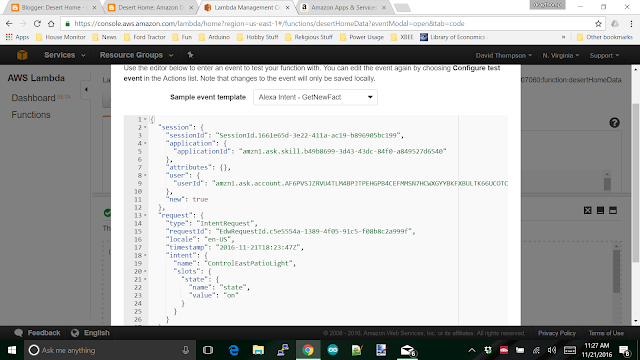
Things like a coffee cup holder for the little tractor, enclosures of one kind or another for the various little computers around the house, custom light switch plate that has a USB plug in it for one of those double outlets, an outside enclosure that will hold an XBee; you get the idea. I've spent hours scanning the web for ideas about enclosures and there just aren't many choices, and the choices there are, frankly, suck.

I don't plan on being the worlds greatest enclosure designer, but it would be great to hide the wires and switches inside something.

But, since it would be a tool, not the focus, I couldn't see spending over a $1000 for a reasonably good printer that I wouldn't have to babysit and nudge all the time. Since I wouldn't spend the money, I decided to use credit card points to buy the printer. It took years to get enough to buy the printer ! Those points don't add up very fast.

Once I got the points, I was up to my neck in various projects around the house that were causing me to spin in circles accomplishing nothing, so I decided to force myself to finish certain projects before I was allowed to order the printer. The well repair got in the way, I also got some very heavy duty shelves for the garage, some serious repair work on the pool filter, and a big storage box for my toy hauler, but I finally finished them. A couple of days ago, the printer arrived.


I got the Flashforge Dreamer basically because of the reviews. There are certainly better ones and cheaper ones, but at some point, you have to make a decision, and good or bad, this was the choice I made. Needless to say, when the printer arrived I unboxed it right away and hunted down the test print.


I did that! Sure, it was composed by someone else, and all I did was print a file, but after literally years of postponed expectations, I finally did it. Dual extruders and different colors of filament and totally enclosed, oh my. (misquoting Judy Garland in the Wizard of Oz a bit).

There's company visiting, so I don't get to spend much time messing with it, but I did create my first little box.


It's about the size of a quarter; too small to actually use for anything, but I drew it and printed it. No, darn it, it wasn't easy. I started off with FreeCAD and got totally lost in the intricacies and nit-picking of design rules. What the heck is a closed polygon anyway?
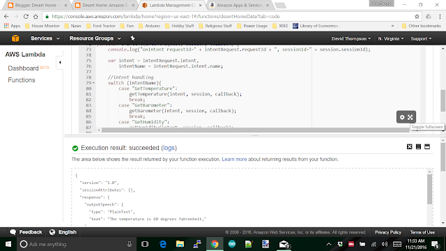
OpenSCAD is very compelling because you basically program the print. I could probably do that, but I really wanted to be able to just click on an object on the screen and move, stretch, or spin it until it looked like something I wanted to print. Lots of modelling software is geared towards creating characters for games. I'm not at all interested in the skin texture of some scantily dressed teenagers dream girl for a video game. Plus, that software is really, really complex. I want to print things, not spend weeks designing a facial scar for the burly hero of the latest version of Doom. On second thought, maybe the dream girl could be a project later.
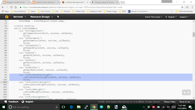
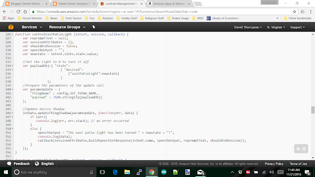
In simple desperation I started using Tinkercad on the web. I'm not happy with it being a cloud based tool, but it will do for now. As I gain experience, I'll probably change to something else, but at least it was simple enough to get me started.

The box and lid above was done with Tinkercad. I got the box on the first try, and I based it on a box a friend of mine made me a couple of years ago. The lid, well that was another story:


The first one was too long, and I forgot a bevel. The second one was too long. the third wouldn't slide in at all, to big. etc. It took five tries to get it good enough. Now do you see why I started with a tiny box? I didn't use much filament (more is on order already) and I learned a heck of a lot. Plus, it didn't take five hours to print the thing. It's really disappointing to spend that much time and find out you missed the screw hole by 5mm.

The slide on lid is sort of the idea I want to use for my temperature sensors. Mount everything on the lid, screw the lid to the wall, and slide the box over it. Simple to mount, simple to open, and mounted to something so I don't keep knocking it off the bedside table. What else could I possibly want?

Since I've got relatives staying with me right now, I can't devote hundreds of hours to working out the details, but I can sneak in a little time now and then to play with it. It's funny they don't complain about the smell of melted ABS at all.

This area has an excessive heat warning for the next week. The local weather predicts temperatures as high as 120F (that's 48C to most of the world), so I guess I'll be inside for the afternoons.

Guess what I'll be doing.

Speaking of Tractor Hydraulics ...

$
0
0
A while back I bought an old, big tractor. I already had a small landscape tractor, but I wanted to be able to dig in this rocky soil and the little one just wouldn't cut it <link>. This big guy had been poorly maintained for many years out here in the Arizona sun and has been a constant pleasure for me to mess with.

But, wait, how can a poorly maintained tractor be a pleasure? In case you haven't noticed, I like to fix things; especially things that I know little or nothing about. I get to dive in, take it apart, figure out how it works, and eventually, actually use it for whatever purpose it was intended. This tractor has been a great project machine for the last couple of years and has been running (well mostly) the entire time. It's dug holes for me, the neighbors and a friend down the road; it also moves dirt for folk that managed to get a pile of it delivered to start a garden. Fun machine.

The valves for the front loader have been leaking the entire time, but hydraulic fluid is much less expensive than the $1800 valve assembly, so I just lived with the leak until about two weeks ago. I had several choices, replace the valve, fix the valve or install a different valve. Each choice, naturally, had its own shortcomings:

If I replace it, I'd have to shell out $1800 plus shipping for a new one. There are a few used ones that show up from time to time on ebay, but who knows their history? I'd have a new valve and it wouldn't leak.

I could send it to a hydraulics shop. I called a couple of hydraulic shops and the estimates ran from $700 to $1000 with the caveat that they might have to custom machine some parts that weren't available. That, of course would drive the price up. The up side is that it wouldn't leak.

Replacing it with a different kind of valve would require some modifications to the tractor and special fittings would have to be put in place. This was the cheapest solution in raw money, but would take some plumbing and fabrication time.

I decided to pull the valve loose from the tractor and see how bad it would be working on it. The hydraulics were weird compared to other tractors of the same era and the valve assembly was a lot larger than I initially thought. I just put it back on the tractor thinking I would decide later (after a couple of quarts of hydraulic fluid) which route I would pursue.

But (there's that word again), after putting it back, the front bucket wouldn't hold position. I noticed it throwing away a pile of weeds. I put the bucket about a foot off the ground in the up position and went to get a wagon load of weeds. When I got back, the bucket had rotated down.

After rotating the bucket up again, I put the weeds in the bucket and went to get another wagon full; when I got back, the weeds were on the ground and the bucket was down again. Taking it for a test drive, I found out that I had to rotate it back up every few minutes or it would wind up facing the ground. The arms worked fine, it was just the bucket that was trouble.

My trouble shooting skills kicked in and told me that messing with the valve put it over the edge and it was time to make one of the decisions above, so I decided to rebuild it myself instead of taking it to a hydraulics shop. Yep, that was choice number four that I hadn't thought of before.

Out came the big tools and cheater bar, and about an hour later I had the valve free from the tractor. The idea was to pull it apart, replace the various o-rings and put it back. So much for plans.

Here's a top view of the valve assembly:


The two handles are for the loader lift and the bucket tilt. From the back side, it looks like this:


People familiar with tractors might notice a couple of things. There are the usual 'work' ports, two each for the loader up down and bucket rotation cylinders and an input port for the fluid. What isn't there is the output port to return the fluid back to the system. That can be explained by this picture of the mounting plate after the valve was removed:


See the hole in the middle of the picture? It's the relatively clean black spot. That's the return line; they actually fed the fluid through the mounting plate to a pipe that leads to the frame of the loader where the reservoir is. This has the advantage that it will not rot in the sun and the disadvantage of making the valve almost impossible to replace with something else. Probably wanted to ensure the sale of parts later.

Here's the valve after I got it out:


I carried it inside the garage and started taking it apart. But before I show you the guts of the thing, I want you to notice the fitting on the very lowest part of the valve body in the picture. Doesn't that look like a galvanized pipe fitting? It was. Here's another view of it while it was still on the tractor:


I knew this wasn't supposed to be there, but didn't really understand what the problems might be. Notice the wet fittings from the leak; I have to keep in mind what the actual problem was I was trying to fix.


These are the two 'spools' that are the actual moving parts inside the valve body. The cylindrical cuts in them allow hydraulic fluid to move to the inputs on the cylinders depending on where you have the control levers positioned. The galvanized fitting is right there at the bottom of the spool on the right. I hunted down a parts diagram of the valve assembly to see what was supposed to be there:


I wrapped a red rectangle around parts that were missing. What happened was that the end cap (20 on the drawing above) was taken off and probably lost. The other parts (17-19) probably went with it, so they sealed that part of the valve body with a kludge of galvanized pipe fittings. Naturally, pipe threads didn't match the threads of the valve it was a little bit too small, so someone wrapped the fitting with about three yards of teflon tape and screwed it in that way.

This was the cause of the bucket rotating down on its own. When I took the valve off the first time I probably bumped the fitting and it moved enough to cause a small fluid flow, just enough to cause the bucket to move slowly. When I messed with it the second time the already deteriorating teflon tape turned into slime and just came apart. Its that pile of stringy looking stuff in the spool picture above. Here's a closer look:


I also found my leak:


I used a flashlight to give you a better view. That hole in there is where the seal for the top of the valve should be. That little pile of black debris down below it is what was left of the seal. All the top seals were that way, brittle powder. It's actually a wonder that the leak wasn't much worse.

So, there I was. The valve had over 200 bucks worth of missing parts and a bunch of cheap seals and o-rings that needed to be replaced. Roughly a couple of weeks wait for delivery and a few hours of work.

Naturally, I decided to take a totally different approach. I ordered one of these:


This is a 24 gallon per minute, double spool valve assembly. Brand new, latest technology and a JOY STICK ! For some work in re-plumbing and mounting this, I'll have the latest in loader control. Yes, it'll cost me about $100 more to do it, but this is just another project to have fun with.

Now, I'm pacing the floor waiting for it to arrive.
Viewing all 218 articles
Browse latest View live