Quantcast
Channel: Desert Home
Viewing all 218 articles
Browse latest View live

Apple Device: "Charging is not supported with this accessory"

$
0
0
I don't have a single Apple device in my house, no iPad, iPhone, iPod, iAnything.  I don't even have any apples.  However, the little wall warts I bought <link> have a bad reputation because they don't work on some iDevices.  While it's true that they don't, it really isn't their fault, it's Apple's.  This is the message:
Notice that it doesn't say that the device is the wrong voltage, wrong polarity, or wrong anything else?  That's because the device just doesn't meet the Apple standards of being made by Apple specifically for a particular Apple device.  They really, really want to lock you into buying your stuff from them and them alone.

My little chargers are fine and will work with Apple stuff with a simple modification that I won't do since I don't need to charge Apple devices.  What Apple did was use the D- and D+ (the two middle pins on a standard type A usb plug) to supply specific voltages that Apple could look at to tell if the charger was one of theirs.

Well, this little trick didn't last long before the engineers that make battery extenders and chargers figured it out.  Obviously, they grabbed a real apple charger and ripped it open to see what kind of shenanigans Apple was up to.  One manufacturer Lady Ada wrote up a nice description of what was happening and how she worked around it for one of her products, the MintyBoost.  She has a nice description of how she overcame the problem and made her stuff work <link>.

This also explains over 90% of the complaints on the web about various iDevices not working with a charger.  Basically, these two voltages (D1 and D2) are tiny and can vary a lot based on contact resistance, length of cable, net draw of the device, etc.  Basically any darn thing at all.  For example some of the solutions are to turn off the iPhone, plug the cable and charger into the phone, plug the charger into the wall, turn on the phone, repeat a number of times to allow the gremlins to align correctly.  And, this occasionally works.  Another solution is to lower the screen intensity, put the phone in airplane mode, then hook up the charger. There's always someone that says you need a new cable, better charger, or hold your mouth differently.  In the case of the iPhone, there was an OS update that caused a significant number people to have charging problems.  The fix for many of these non-technical folk was to go to the Apple store and get a new device or have a new part installed that will work.  Of course there are the Apple cultist that insist that only a new Apple charger will solve the problem.

But people, electrons are electrons and it isn't you or your device when a problem like this turns up, it's Apple exercising their control over their cult.  Annoying.

Don't despair yet.  There are ways to get around this problem that actually make sense.  No, you don't need to wet a Qtip with perfume and clean the contacts, letting it air dry for an hour(this is a real suggestion), there are much more mundane solutions.  For example, this site <link> talks about a little connector that has Apple plugs on both ends and works around the problem.  However, the darn thing is too expensive (I'm not a fan of this solution, but some of you might be).  There are several other similar devices out there that solve the problem.  You can also solve the problem by building something yourself (gasp !); I know this goes against life philosophy of the myriad teenagers that talked their parents into getting this cool new gadget, but life isn't fair.

Just cut a USB charging cable that mates with the device and add a little voltage divider.  The schematic of the changes is:
If this picture doesn't look familiar, take another look at Lady Ada's description, it was taken directly from there.  See, Apple uses the voltage divider to set specific voltages on D+ and D- to identify their devices.  Other manufacturers don't do this kind of thing unless they're trying to meet the USB charging standards, and for a low price device it isn't worth the effort or cost. Just another effort of Apple to wrangle you into their pen.

So, you ask, "What do you care, you don't own an Apple device?"  I don't, but my less fortunate friends, neighbors, and relatives do.  They get really annoyed when their devices won't work on one of my chargers when they come to visit, and they hate it when a charger stops working and gives them this silly, non descriptive message.  Also, I found zero, nada, explanations of what was going on to help people with this problem.  That annoyed me more than anything else, so I decided to post it here and a couple of other places, hoping that poor souls that are eating up Google cpu cycles could, at least, understand the problem better.

Soak a Qtip in perfume and clean the contacts?  Really?

Battery Charging - Part 5 (Harbor Freight item 42292)

$
0
0
Yes, I finally assembled and tested the various ideas into a single box for my float charger for lead acid batteries.  This project has been going on for over a year now and may be getting close to having a nice working prototype.  I incorporated a voltage display and an XBee set up to transmit analog readings into the mix.  So, what happens is you plug the charger into the wall and the XBee comes on, samples the voltage before the output diode and sends it to whatever device you set it up to talk to.  This way I can monitor the battery state of charge remotely without even having to go into the garage.  Here's an interior view of the charger:


On the lower left is the charging circuit that I came up with based (roughly) on the Harbor Freight 42292; at the top, stuck to the side is a series 2 XBee plugged into a breakout board; and on the right is the voltmeter display.  This is all enclosed in a plastic rectangular enclosure.  When assembled it looks like this:


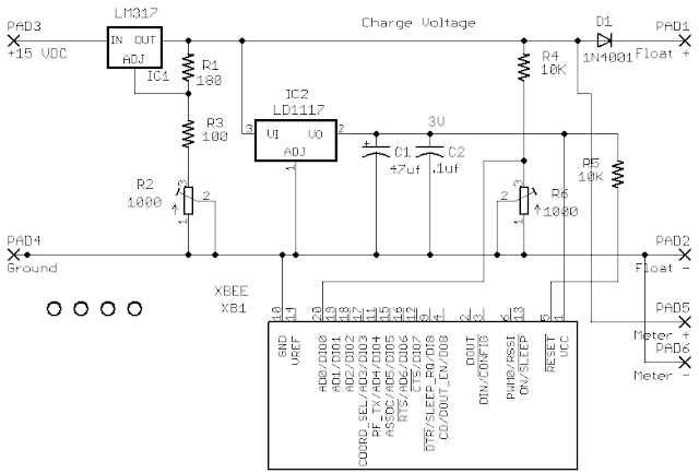
Of course, since the XBee is a 3.3V device, I had to add a power supply for it.  I took the power directly from the float voltage and used an AP1117T33 regulator.  When I first started testing the combination, it got pretty hot pretty quickly, even when it wasn't hooked to a battery.  A little checking (I unplugged the XBee) told me that the XBee and its two LEDs were sucking enough power to heat it up, so I enabled sleep on the XBee.  This way, it would be off most of the time and only turn on to take a couple of measurements and transmit them.  This totally solved the problem.Here's the schematic I eventually settled on.  

If you're following this, you'll see that it's a simple variable supply that I set to 13.4V with resistor R2 which feeds a 3.3V supply to power the XBee.  The voltage divider R4, R5 sets the level that is in the 1.2V analog input range of the XBee.  Since these regulators sometimes tend to oscillate, I added capacitors C1 and C2 just to make sure I didn't drive the XBee nuts.  That's also why I added the resistor R6, to keep it away from reset.

To set it up, I put a 1K resistor across the output and set the voltage using R2 to 13.4 volts.  Then I centered the pot R5 and checked what was being transmitted.  By adjusting the pot, I was able to get a nice reading at the receiving end which I translated back into voltage and can display with an XBee connected Arduino.

There's a little jitter in the XBee readings caused by transients.  I can solve that two ways, add a capacitor on pin 20 of the XBee or do a rolling average on the receiving device.  I haven't decided which to do yet. I'm leaning toward a rolling average, but experience will tell me if it even needs to be fixed.  Here's a short sample of the Arduino output I set up.  Obviously, this isn't what I'll eventually use, but it's nice to be able to see the charger out in the garage:

A fun item I noticed is that the circuitry for monitoring the battery and transmitting the value can be separated from the charger.  That way I could hook a device to the battery and it would transmit the voltage to something that could alert me to go attend to the darn thing.  I may pursue that for something in the future.

No, I'm still not done.  This thing was a real pain to build.  It came up from several prototypes and kept getting more complex and looks like a mess because of this.  I think I may journey into getting a custom PC board made to put the thing together with since I want at least five of them.  Also, since I now have a box that will hold it, I'm going to mount the components on the lid with a wire to the display on the box part.  That way I can actually screw stuff down so it doesn't bounce around over time.

Alternatives to Cosm (Pachube), Part 2

$
0
0
(edited heavily on Dec 11, look below to see why)
Previously <link> I discussed the possible use of Sen.se as an alternative to Cosm.  This is becoming important to me because Cosm seems to be slowing down over time.  The users on their forum have brought this to the developers attention and there have been responses, but I'm having trouble loading a single day of data without a server error and failure to display the data.  So, I just tried out another offering emoncms.org.  It's pretty darn compelling.

The problem with most of the services that I've investigated though is there just isn't enough documentation on what it does, how it does it, where it stores the data, etc.  This is somewhat true of emoncms, but at least there's enough (including its forum) to actually use it.  It took me most of an afternoon to prowl through enough documentation and user comments to get it working.  The part that held me up the most was finding out how to get my data to the service.  It turns out that it's relatively easy to have an Arduino send the data to the service and then construct graphs and things using emoncms tools.

However, there are a number of odd problems relating to embedding their graphs into a blog page.  When I first put this page up I had a multigraph and a gauge that showed real time usage.  The problem was that using the scripts turned off the scroll bar for the page.  That's a bit unacceptable, so I edited the page to remove the visual display.  There are also a few display problems when using their dashboard, but it mostly works.  Here's the link to my dashboard with gauges and graphs that indicate real time data <link>.

Like I said, this is a very compelling site.  One problem may be that this site is open source and maintained by a community of interested users.  That means that it will grow quickly and capabilities will be added as they are thought of and users make the changes (unfortunately, it's the same for bugs).  That makes it somewhat unpredictable.

I can deal with that.


Like I said though, it's a bit tough to find out how to send data from an Arduino to the site.  I got it to work with minimal trouble after searching a lot on the site and its forum.  Here's a code snippet to illustrate how to do it:


The Arduino Sketch

void sendEmoncmsData(){
  char dataBuf[100];

  if(emoncms.connected()) // already trying to get data, just leave
    return;
  // construct the data buffer so we know how long it is
  strcpy_P(Dbuf2, PSTR("{RealPower:%d, PowerFactor:0.%d, PowerVoltage:%d.%02d, PowerFrequency:%d.%02d, InsideTemp:%d, OutsideTemp:%d}"));
  sprintf(dataBuf,Dbuf2,
    (int)round(realPower),
    (int)(powerFactor*100),
    (int)rmsVoltage,
    (int)(((rmsVoltage+0.005) - (int)rmsVoltage) * 100),
    (int)(frequency),
    (int)(((frequency+0.005) - (int)frequency) * 100),
    (ThermoData[0].currentTemp + ThermoData[1].currentTemp)/2,
    (int)round(outsideSensor.temp));
    Serial.println(dataBuf); // take this out when you've got it working
//    return;  // so you can see the buffer before you actually send it
  strcpy_P(Dbuf,PSTR("emoncms Connecting..."));
  Serial.print(Dbuf);
  if(emoncms.connect()){ // set a limit on how long the connect will wait
    strcpy_P(Dbuf,PSTR("OK..."));
    Serial.print(Dbuf);
    tNow = now();
    strcpy_P(Dbuf,PSTR("GET http://emoncms.org/input/post?apikey=secretnumbers &json="));
    emoncms.write(Dbuf);
    emoncms.write(dataBuf);
    emoncms.write("\n");
    emoncms.stop();
  }
  else {
    strcpy_P(Dbuf,PSTR("failed..."));
    Serial.print(Dbuf);
    emoncms.stop();
    while(emoncms.status() != 0){
      delay(5);
    }
  }
}

See, it's a simple json interaction that names the variable that you want to save data for.  emoncms will create the data store and name it for you.  All maintenance for the data can be done from their site.

This could well become my new cloud storage for data.

Let's Talk About Septic Tanks

$
0
0
Nice subject....right?  Since I live out in the sticks, there are no services here except power and phone.  I have my own well, propane tanks, and septic system.  Since it's a relatively new septic system, it has all the new and improved features.  This usually means there is more to worry about and take care of, and at least in my case, this is certainly true.

My first problem came a few years ago when sewage backed up into the house.  Since I had only a general idea where the tank was actually located, the service guy had to hunt a while to find the access ports on the tank.  See, newer septic tanks have two access points for different stages of sewage treatment and both of them have to be pumped out.  When he uncovered it, I found out I had a filter inside the tank.

Yes, there is a filter that stops solids from making their way out into the leach field.  The filter had plugged up and was not releasing fluid into the leach field.  That filled the tank and caused me to have a mess in the bathroom.  Nice.  So, obviously, the tank filter needed to be cleaned and the tank pumped out to restore service.  So, I had the service company install risers with nice green covers on them to allow (relatively) easy access to the septic tank so I could clean the filter.  Total bill, around $800.  Not something I wanted to repeat very often.  Here's a picture that illustrates the kind of thing I'm talking about:
All you see at ground level is the green plastic covers.  Just remove these to service the tank.  Here is what the filter looks like:
To clean it, just grab the blue handle, pull the filter out, and bang it around.  Once you knock the debris off, rinsing it is easy, just spray it down with a water hose.  Here is the basic configuration of the tank and the various parts inside:
Except I have a riser on both sides so each tank can be easily pumped out.  Notice the 'sanitary tee' on the inlet side?  That causes problems as well; more on that below.

Fast forward a year.  I had company with kids and the darn tank filled up again.  I opened the wonderful new access points, and sure enough, the tank was full again.  Called the same service company and they came out and cleaned it out for me again.  I chose this solution to get the house working again since I had company at the house that needed to use the bathroom.  Total bill, $340.

A couple of weeks ago, it happened again.  This time I didn't have company, so I went out and cleaned the filter.  The tank immediately started to drain into the leach field and drop the level, and by the next day, it was back to a normal level.  No costs, this is the way to do it.  However, about four days later the house backed up again.  When I opened the access point, the tank was at the proper level, and the filter was clean.  What the heck was up with that?

Seems when the tank was full, a clot of toilet paper formed on the inlet side and had turned to concrete.  See, what happens is that the 'sanitary tee' caught all the toilet paper and allowed a plug to form on the inlet.  When I lowered the level of the tank, the plug hardened and I had a new problem to deal with.  I spent most of the day with a water hose and jet nozzle breaking up the plug and restoring septic service to the house.  This needs some solution that doesn't require me to remember that the darn filter needs to be cleaned, and a way of clearing the pipes that doesn't entail a days work with a water hose.

So, I bought one of these:
This is a hose and special jet that you hook to your power washer and run through the sewer system to clear out clogs.  It won't work on tree roots or cave ins, but it will clear most clogs quite nicely.  Since I had never used one before, I was skeptical, but it did a great job.  It pulls itself along breaking up stuff and washing it down the sewer line.  If it stops at a bend or a clog, just pull it back a little bit and let it go; it will work its way through the clog and around the corner after a couple of tries.  Really nice tool.  Total time to clean out the pipes was around 30 minutes and most of that was figuring out how to hook the device up to the power washer.

But, to prevent the problem from sneaking up on me and flooding the bathroom was still a problem.  With a little searching I found out that there were floats that are specifically designed to tell you when the septic level rises.  I got one of these:
This is a normally closed float switch.  I chose normally closed so that I would know that the level was OK by a closure and it would open when the level got too high.  This way I knew the switch was OK and wouldn't have to wait for the sewer to back up to find out the switch was broken.

Total cost for both items: $150 including shipping.  I consider this a wise investment since now I can tell if the tank is rising and clean the filter long before it backs up into the house.  I also have a way of clearing the pipe easily each time I open up the tank to prevent the toilet-paper-turned-to-concrete-plug problem.  Sure, I could just clean the filter every six months or so, but who remembers that kind of thing?  Especially since this is probably the nastiest job one can take on around the house.  'Sanitary tee' ?  Who the heck thought of that name?

I haven't hooked the float into the house network yet, but that will come over the next month or so.  That's a problem that I already know how to deal with.  I plan on having a little light come on somewhere inside the house that I can't ignore; heck, I may have it send me email also.

I have the coolest septic tank in the area.


Really Nice Gauges

$
0
0
Recently I was shown an extremely nice set of gauges by a fellow on the Arduino forum, graynomad.  They were metalic looking and had a great set of parameters to mess with.  Well, I couldn't resist, and decided to figure out how to use them and somehow get them on this site.

Well, I sort of got it working.  It seems that Google (Blogger) has a problem with iframes, and that's pretty much the only way to include one of these.  The problem is that it messes with the scrollbar in Chrome, their own browser.  I'm not sure how they show up in IE, except they won't show up at all in IE8 because it doesn't support canvas.  For something this complex, the canvas is the only practical solution short of using something like Flash.

So, if you're using Chrome, look over to the right where the scrollbar is, notice it doesn't look right?  If you put your mouse over there and click, you'll see that it actually works, but just doesn't look right.  I don't have a solution to this yet.

But, let's look at the gauge.  Notice it has an LCD display and a moving hand.  When my energy usage goes above the red indicator (it's on the dial), the little red LED will light up.  These are all parameters that can be set for the gauge.  I chose the brass look simply because it fit my taste, there are many, many combinations possible.  The gauge is sort of real time.  What I do is update it every 10 seconds from my datastore at Cosm which is updated every 60 seconds.  So, every minute or so, it will be updated to reflect the current power usage at my house.  I plan on working with these gauges quite a bit more; they're just too nice to leave alone.

So, if you want to use them also, or just admire the tremendous amount of work that went into creating them, they're known as the SteelSeries and apparently were initially designed for weather displays.  Just go to Google and start looking.  If I gave a URL, it would be the wrong one or outdated or something, so check it out yourself.

And, sorry about your scrollbar; it'll come back when you go leave this page.

Let's Examine My Power Usage

$
0
0
After a couple of years of monitoring my power closely and installing various devices to check, examine, and control this usage; what have I learned? Let's walk through a typical Friday. I choose Friday because it's a weekday where the power company enforces demand billing and it's winter and getting cold here in the desert. I'll do something similar in the summer as a comparison. First, here is a graph of the power usage for the last 24 hours:

Yes, at 10PM last night I had spikes in my usage; I was doing laundry.  The spikes are the clothes dryer switching it's element on and off to dry the clothes.  Notice that the spikes are hitting around 7.5Kw?  That's a heck of a lot of power.  I do the drying at night in the winter to save some of the heat inside the house; not all of it gets blown out the vent into the air.  Immediately to the right of the dryer, the heater kicked on and stayed on until 1:15AM.  The heater uses around 4Kw, and since it was cold, stayed on for quite a while.  Then there was a low period for a couple of hours with only the recirculation fans running before the heater kicked on again and ran until almost 9:00AM.  Notice that the temperature took a quick upward climb at the same time?  That's when the sun finally came up over the mountain to my East and hit the house.  There was another period after 10:00AM where the wind got up and the cold breeze caused the heater to kick on again.  When it was getting close to noon, the heater came on, but the peak demand controls I have built into the house kicked in and shut it off at noon.  From noon to 7:00PM the demand is held low, less than 2Kw to save cost.  Then at 7:00PM, the recirculation fans kick back in and start equalizing the house out again.  The huge spike just after 8PM is me making a pizza.  The narrow spikes in the period from noon to 7:00PM is me doing a little welding in the garage.  Yes, I have projects that aren't electronic and require the use of tools bigger than a soldering iron.

Some people may criticize me for the amount of power I use, but I didn't create these appliances that pull 10Kw doing some task.  It takes a lot of power to run an electric clothes dryer, electric oven, microwave; people just don't think about it until the bill comes in.  I've seen consumption at my house exceed 20Kw.  When I have a cold evening and both heaters are on, I have clothes in the dryer, and decide to bake cookies, the usage can easily top 20Kw in short intervals.  Do you realize that is more than 200 amps coming in the power lines?  And this is not an unusual thing for people to do.

Now, do you understand why I have automated controls in place to keep this in check?  Heck, I complained to one of my neighbors about my power bill coming it at around $117 last month.  I actually thought they were going to attack me.  It seems their bill for last month was a little over $350.  

A couple of months ago the power company wanted me to install a smart meter to, "better control my power usage".  I asked them to pull up my records and take a look at them over the phone.  The 'Energy Usage Advisor' was astounded at the controlled usage my bill reflected.  I asked him to show me an example of what their smart meter with household controls could do....crickets chirping....  No, they couldn't show me anything that even came close to the level of control I already have, and I ain't even close to being done with the project.  See, the power company wants to control the temperature inside my house, limit the usage of large appliances, and put special controls on my swimming pool to "Save me money and lower my carbon footprint".  Yep, I'm going to let that happen (not).

I'm not going to get into one of my lectures about letting a corporation control anything inside my house.  How things like 'carbon footprint', 'impact on environment', and 'delayed usage' I consider to be buzz words that let them get into and try to control my life for their benefit.  Heck, if they had built the power plants back when they were cheaper, before inflation and needless regulations force prices to skyrocket, we might not be in this mess.  But, no, they wanted to delay it as much as possible.  

Needless to say, I don't have a smart meter at my house.  If I did, these smart meters use Zigbee communications to control things.  Heh, heh, I have a full dozen Zigbee devices in my house; how long would it be before I was feeding them the data I wanted them to see.

Have a nice day power company 'Energy Usage Advisor'.

Alternatives to Cosm (Pachube), Part 3

$
0
0
Found another one to try out.  The site thingspeak.com has apparently been around a couple of years, but didn't turn up on any of my searches.  I stumbled across it today and had to go try it out.  After a number of false starts and some serious reading, I managed to create a data store and put some data in it.  Then began the laborious task of modifying my House Controller to send data to it.

You'd think I'd be getting pretty good at this by now, but I tried for two hours to get data to upload to the site with zero success.  Then, in typical form, I went back to beginning, found my silly mistake and got it to work.  This site works like Cosm.com in that you construct a POST and include the data to send it.  They use fixed field names field1, field2, etc. instead of numbers and the data doesn't have to be constructed in a JSON format, just named as parameters.  I'm using something on the order of:

("field1=%d&field2=0.%d&field3=%d.%02d&field4=%d.%02d&field5=%d&field6=%d")

to send the data (hope you understand printf).  This is actually easy to understand and could work quite nicely.  Yes, they have embeddable charts.  Here is a daily chart of my power usage with their facilities:


The extremely cool thing about their charts is that, if you set them up for it, they are dynamic.  That means new dots will appear in the chart as my house updates the data on their site.  If you put your mouse on the chart and move it around, each of the datapoints will be highlited and the actual data will be shown.  This is really a nice way to chart the data. They don't have the ability to zoom in on the data or subset it by manipulating scrollbars or highliting areas, but the ease of making charts if phenomenal.

There are a number of other features to play with.  They even let you record a status for the data being sent. This is a text field that can be retrieved and displayed.  So, I could display, "Currently Offline" on a feed that was having trouble if I wanted to.  There's also an API for location data for things that move and an interface to twitter for people that like that kind of thing.  I haven't found any use for a twitter interface at all, but someone must like it since it turns up all over the place.

The site supports JSON data retrieval so it can be used in a plugin.  This is different from the emoncms.org site.  Security of one's data is a serious concern, but it's not much use to put data out there if you can't get it back to be used.  That's the most serious problem I ran into with emoncms.  The fact that you can get the most recent data back gives you the ability to do this:
This is an iframe that contains an AJAX query that fills in the value for a SteelSeries gauge.  I have this on a cloud server so that I can use it anywhere by just pointing to it.  The site, thingspeak.com, takes care of automatically updating it, so this is updated periodically with the data my house sends up.  I could (relatively) easily construct a AJAX query that would feed into the Google chart API and produce one of their great charts with zoom and everything.  That is currently left as an exercise for the student.  Wait long enough and I'll probably do it.

So, I've researched and actually set up data stores on several of the repositories out there.  They each have something unique to offer and seem to do the job of holding, displaying, and supplying data.

Try them out and have fun.

Part 2 of this effort <link>
Part 1 of this effort <link>

Speaking of Electrical Appliances

$
0
0
My previous post on my electricity usage got me to thinking about appliances and how they use power.  This is a chart of my usage today.  The spikes are my electric range.  I cooked a pork butt roast (actually, it's the shoulder of a pig) in a Dutch Oven at 275 for most of the day.  I do this so the meat is really tender and just falls apart.  This gave me an opportunity to examine how efficient the oven is over a long period.

Turns out, it's not too bad.  As long as you keep the door closed and don't constantly check it to see how it's doing, the device works pretty well.  Notice on the left there is a wide spike of about 5Kw to initially heat the oven; then spikes at about 15 minute intervals.  There is a double spike at just before 2PM when I opened the door to check on it.  These spikes use a lot of power, for a very short time.


I don't have an easy way to measure the usage over all since the levels change so much, but it looks like the oven is very efficient.  Those little spikes, when expanded are less than two minutes long and shouldn't cause to much usage.  They look really huge, but actually they don't represent much power.

Unlike the compressors for the heat pumps on the house which run for hours at a time in the winter and intervals measuring several minutes in the summer, this is an extremely short period.  I need to measure some of the other appliances that really chew up the power, I may be able to reduce my power bill even more.  Things like cooking in the morning during the week to build up some heat in the house to help during the after noon may work well.

But, winter is almost over for me.  Notice that it got up to 82F today; this is the middle of January.  I just love Winter in the desert.


Water Heater Power Control

$
0
0
In the last post I talked about how short burst of high power usage can be OK, but long periods of high power usage can kill me.  Remember, I'm on demand billing where they average the usage across every sixty minute period and charge me a ton of money if I let my peak period usage get too high.  I discuss this extensively on my Power Usage page <link>.  I've managed to keep it at or under 2Kw for quite a while and saved a lot of money on power bills.

However, the water heater has been a continuing problem.  I have a solar water heater for the house and it will make hot water for free if there is sun.   One wouldn't think that is a problem here in Arizona, but occasionally we get several days of overcast weather and that means no hot water.  The water heater works great if there is sun, even if it's 30F outside.  The collector temperature goes up to 150F pretty quickly and that's enough to create plenty of hot water.  When the weather is overcast and especially when it's rainy, the collector won't generate any hot water and I have to rely on a heating element inside the device as a back up.  Obviously, I don't want that heating element drawing power during the peak period because it will pull at least a couple of Kw and mess up all my work saving power.  I actually had this happen once <link> and it cost me a whole lot more than the water was worth.

At first, I had an Intermatic timer that worked quite well, but since I live in the realm of power failures, it wouldn't stay on time.


If I lived where the power was more reliable, this would have been fine, but I often lose power during thunderstorms and sand storms, so I looked for another solution.  Since I had X10 controls in the house to operate the outside lights, I went with that solution.  Yes, I could have gotten a digital timer for the water heater that has a built in clock with battery backup to keep the time, but I had already given up on a $60 device and I didn't want to spend that much again.  I got an X10 appliance module from an ebay vendor, a contactor from an A/C supplier, and an electrical box from a neighbor and built a remote control for the water heater.  Frankly, I didn't save any money, but I had remote control and my light timers for the house could turn the power on and off to the water heater.

X10 sucks.  Sure, that's a little severe, but if you're using it for anything that isn't monitored all the time, you have trouble.  X10 will false, fail to receive, and just refuse to work.  In unattended circumstances, this will turn on lights, leave them on when they're not supposed to be, and turn them off for no reason at all.  Same with water heaters.

So, last Saturday I decided to turn on the water heater for the day to get enough hot water for a nice long shower.  It wouldn't turn on.  I even changed the appliance module, but nothing seemed to work.  It was chilly, and raining, but I turned off the breaker, dried off, and bypassed the stupid thing to force the water heater on.  Then, I started reprogramming my Garage Controller <link> and House Controller <link> to take over this job.  I had two unused relays in the garage controller and lots of memory on the House Controller, so a little rewiring and programming and I had control of the power to my water heater.

I use regular text transmitted from XBee to XBee to control and monitor status for the various controls I've built around the house, so every 15 seconds or so, the garage transmits: 'garage,closed,closed,off<cr>'
with the items being the two garage doors and the water heater, so it knows the state of the garage devices.  To change the state of the heater, I have the controller transmit, 'waterheateron', or 'waterheateroff'.  Using text like this allows me to debug things with a sniffer <link> that I can watch the various devices with.  I can also transmit the commands by hand using the XBee X-CTU configuration tool.  All of my household commands are sent in broadcast mode so they can be seen by any device.

I also added items to the web interface the House Controller supports so that I can see the state of power to the water heater using a web browser.  There's also a button to turn the power on and off as needed.  This means the house controller can schedule power to the heater as needed with the garage controller having final say in the situation.  For example, I have the water heater hard coded to turn off just before the peak billing period and back on just after.  This keeps the water heater off when the prices are high.  If the power fails, the water heater defaults to off; I may change that if it becomes a problem.  Here's a picture of the Garage controller with the new wires in it from the water heater:

And here is the electrical box that houses the contactor that actually controls the power to the water heater:


I still have one relay left in the Garage Controller, wonder what I'm eventually going to use it for.


Outdoor Temperature Part 3

$
0
0
Part 1 is here <link>, part 2 is here <link>

I've been asked several times now how I mounted the temperature sensor to the XBee, and I didn't explain very well because I was too lazy to take a picture.  See, once I put it in a Stevenson Screen and mounted it on a fence post, it isn't as easy to get to as a lazy person like me would like.

Well, I got asked again and decided to bite the bullet and go open it up for a picture:

Simple huh?  One end of the sensor is hooked to 5V from the wall wart, the other end is to ground and the sensor output is connected to two 10K resistors in series to ground.  I take the center of the the two resistors to an XBee analog pin for transmission to my House Controller.  Notice the sophisticated nylon tie to mount the XBee?  Remember, this is all inside an open air enclosure that is screened on the inside to keep the darn birds from building nests inside.  It also keeps out rodents and bats (yes, I know bats are rodents).

The board is an XBee breakout board that has a 3.3V regulator on it to power the XBee, so I have access to both 5V and 3V to power whatever I need.  I've mentioned the wall wart several times on this blog, so look around a bit if you're curious.

There, now I can just point to a picture when people ask how I did it.

Ethernet, Running Out of Connections

$
0
0
When I added thingspeak <link>as a repository for my data online, I started to notice that my House Controller <link> was freezing up and rebooting pretty often.  This isn't as bad a problem as one would think since the arduino only takes a few seconds to reboot and will continue right where it left off with only a minute or so worth of data lost.  However, it drove me nuts after a day or so of watching it randomly reboot for no apparent reason.

I moved the controller over to my breakfast table and plugged it into a laptop to monitor what was happening.  When the problem happened, it seemed to be at 10 minute intervals, but sometimes it would be at a minute interval.  What the heck?  I finally noticed that it was happening when the controller was doing a lot of internet interaction.  This made sense because I had recently added updates to thingspeak, so maybe I had screwed that up somehow.

Well, I finally had a brainstorm and realized that I was running out of connections on the ethernet card.  I use a 5100 based ethernet card for the arduino.  I use one of the older arduino ethernet cards, and I have heavily modified it so I can tell if the ethernet actually connects OK, and these devices only support four simultaneous connections..  See my page on the Thermostat <link> for details on the modifications I did. I connect to these devices using ethernet:  North home thermostat, South home thermostat, Dyndns to publish IP address, Dyndns to get my current IP address, Cosm, emoncms, thingspeak, and a connection for the web server that runs on the arduino itself. That's a possibility of eight connections, and somehow I must be using them all up.

I was.  I use timers for connecting to devices, and over time, I had too many of them trying to connect, or already connected at the same time.  The web server running on the little machine is always connected; the thermostats are connected every thirty seconds as clients; Cosm, emoncms, and thingspeak, connect every minute; Dyndns is connected every ten minutes and again a few seconds later if my external IP address changes due to my ISP.  Obviously, these were happening at the same time occasionally (often) and the board was running out of connections and pausing which caused the watchdog timer to fire.

I can't emphasize enough how useful timers are.  These little machines don't have an operating system that can handle scheduling tasks or switching between actions that some projects require.  You have to handle all this stuff yourself.  If you want something to happen at noon, you can either wait until your clock hits noon, or set a timer to check it for you.  If you are waiting, you can't do anything else.  Using timers to schedule things allows the little devices to behave like a machine many times its capabilities.  If you're into automating things, you should examine timers extensively.

What should I do?  There are lots of solutions, things like a table of connections that I can check to see if one is available, add a call to the ethernet library to tell me if I have a connection left to use, try and connect then check the return value for the right error, etc.  I decide not to do any of those.  Instead, I staggered the timers such that they split the minute up into intervals where each device could have a clear shot at getting a connection.  This should be fine since the various interactions only take a couple of seconds max and the odds of inserting a new bug using any of the other techniques was extremely high.  My original code to set up the various server interactions was:

Original Timer Setup

void initTimers(){
  
  Alarm.timerRepeat(30, updateThermostats); 
  Alarm.timerRepeat(60, updatePachube);     
  Alarm.timerRepeat(60, updateEmoncms);
  Alarm.timerRepeat(60, updateThingspeak);
  Alarm.timerRepeat(10*60,checkPublicIp);   
  
 /* other timers to control devices follow this */

So, you can see that every minute, I try to update at least 4 devices and every ten minutes, I add a couple more.  The odds of running out of connections (maximum 4) are high; it's a wonder the board stayed up for more than a couple of minutes.

There isn't any good solution to doing this differently using the same technique.  If I stagger the times, it will just be rebooting less often because they will eventually fall in the same couple of seconds; I know, I tried that first.  So, I redid the way the timers are set up:


Modified Timer Setup

void initTimers(){
  // I want the various timers to work on the minute boundary
  while(second() != 0){
    delay(500);
    doggieTickle(); // so the watchdog doesn't time out on me
  }
  // I have to stagger the timers for the ethernet
  Alarm.timerOnce(5, updateThermostats);                           
  Alarm.timerOnce(10, updatePachube);
  Alarm.timerOnce(15, updateEmoncms);
  Alarm.timerOnce(20, updateThingspeak);
  Alarm.timerRepeat(10*60,checkPublicIp);


First, I wait until the time hits a minute boundary by waiting until seconds == zero.  I have to keep the watchdog timer reset during this period to make sure I don't reboot the board.  Then I set timers for the offset from the minute boundary that I want for the various devices.  When these timers expire, I set timers for the next time the device is supposed to run.  For example, the thermostats are handled like this:

The Arduino Sketch

void updateThermostats(){  
// this will interogate the thermostats to make sure data is current

  Alarm.timerOnce(30, updateThermostats);  // check again in 30 seconds.

  getThermostat(0, "status", true);
  getThermostat(1, "status", true);
}


And, then when it cycles around again, a new timer will be set to do the same thing.  Basically, when I initialize the timers, I'm just kick starting an action that carries itself on after that.  This way the devices fire off at certain times within a minute so they don't conflict with each other as much, which should leave me with a free connection or two at all times.

Most people that do this kind of thing use a home computer to collect and forward data; that isn't a solution for me.  I don't want to tie up a large machine doing this kind of service since they can be useful for other things (surfing and games).  That's why I built the house controller in the first place.  Also, laptops and desktops take a long time to reboot and that doesn't go well with experimental software.  Mainly though, what the heck kind of pleasure is there in using a great big ol' machine to do something like this?

For my next project, I'm going to move this device up to the latest version of the arduino IDE.  I've been using IDE 21 for a long time now and the latest is 1.0.3 or something.  They changed a lot of stuff and redid most of the libraries, and I have changed some of the libraries to support my work, so this may be a challenge.

Using the XBee Library Part 3

$
0
0
Part 1 <link>, Part 2 <link>.

As part of my porting of my devices to the latest version of the Arduino IDE, I decided to move the devices to using the XBee library.  Back in part 1 I described why I suddenly took an interest to it, and since I was going into the code, I might as well start using it for real at the same time.  The changes to make my XBees receive packets using the library went without a hitch.  It just worked fine and reduced the code I had to write by a lot.  However, when I looked at transmitting data, I was appalled.  All the examples show somthing like:

XBee Tx Example

void loop() {
  // break down 10-bit reading into two bytes and place in payload
  pin5 = analogRead(5);
  payload[0] = pin5 >> 8 & 0xff;
  payload[1] = pin5 & 0xff;

  xbee.send(zbTx);

  // flash TX indicator
  flashLed(statusLed, 1, 100);


I mean REALLY??  Setting the bytes into an array one at a time?  Well, I went searching the web to see what else could be done and found dozens of examples of this kind of thing.  Here's one from the New SoftSerial example:

Another Example

void loop() {

  payload[0] = 'H';
  payload[1] = 0x7E;
  payload[2] = 0x11;
  payload[3] = 0x13;
  payload[4] = 0x7D;

  xbee.send(zbTx);


I even saw examples that had many bytes filled in one at a time to compose the data that needed to be sent.  Clearly, the examples need to be updated.  That's not something that is easy to do, but I can put an example here to show how a simple string, "Hello World" can be transmitted to another XBee without all the hassle. Here is an extremely easy way to do it:
My Tx Example
/*
XBee RX test for a Arduino Mega2560 using Serial3 as the XBee serial
input for a Series 2 XBee.  This is NOT based on the examples that come with
the Arduino XBee library.

See, the examples there and most other places on the web SUCK.  Andrew's
library is much easier to use than the illustrations would lead you to believe.

This is a HEAVILY commented example of how send a text packet using series 2
XBees.  Series 1 XBees are left as an exercise for the student.
*/

#include <XBee.h>

XBee xbee = XBee();
// This is the XBee broadcast address.  You can use the address
// of any device you have also.
XBeeAddress64 Broadcast = XBeeAddress64(0x00000000, 0x0000ffff);

char Hello[] = "Hello World\r";
char Buffer[128];  // this needs to be longer than your longest packet.

void setup() {
  // start serial
  Serial.begin(9600);
  // and the software serial port
  Serial3.begin(9600);
  // now that they are started, hook the XBee into
  // Software Serial
  xbee.setSerial(Serial3);
  Serial.println("Initialization all done!");
}

void loop() {
  ZBTxRequest zbtx = ZBTxRequest(Broadcast, (uint8_t *)Hello, strlen(Hello));
  xbee.send(zbtx);
  delay(30000);
  strcpy(Buffer,"I saw what you did last night.\r");
  zbtx = ZBTxRequest(Broadcast, (uint8_t *)Buffer, strlen(Buffer));
  xbee.send(zbtx);
  delay(30000);
}


Yes, that's all there is to it; this example will compile and run using IDE 1.0.3 on a Mega2560.  Andrew made the library quite capable, but most people don't seem to want to look deeply enough into it to use it to advantage.  Notice that you fill in the Tx request with an address and then send the string pointer and its length to the XBee.  It's just that simple.  You can use a buffer and format it to be exactly what you want, then hand it off to the xbee.send() for transmission.  Really, really nice.

Remember though this example is for a mega2560 with four serial ports.  To do exactly the same thing on a UNO, just use SoftwareSerial as I described in part 1.  It will work equally well and you still have the Serial to output status and debugging information so you can see what is going on.

Suppose you want to send the packet to a specific XBee on your network, avoiding the problems that can happen with broadcast <link> it's actually really easy.  Just create another address like the one for Broadcast in the example above and use it instead.

Using this technique, I reduced a fifty or so line transmit routine down to:

How Simple It Can Be
XBeeAddress64 Broadcast = XBeeAddress64(0x00000000, 0x0000ffff);

void sendXbee(const char* command){
  ZBTxRequest zbtx = ZBTxRequest(Broadcast, (uint8_t *)command, strlen(command));
  xbee.send(zbtx);
}

Yes, I can compose the commands for my various devices and then just call sendXbee() with the string.  Simple, easy to read, and it works.

I like my little XBees more and more each day.

Still Wrapping up the Mega2560 Bootloader

$
0
0
More on the continuing drama of the 2560 bootloader.  Most recent post on this is here.

I just moved a lot of my code up to IDE 1.0.3 and decided to check and see if they had updated the bootloader in this.  Well, they haven't.  I just used it to program a 2560 and the bootloader supplied with the release failed on both the '!!!' and the watchdog timer problems.

But, I went searching to see if there was some schedule and ran across another bootloader that works.  This one is smaller because the author removed the code that samples for the '!!!' to jump into a rom monitor.  So, there is no problem with '!!!' because it doesn't look for it, and the watchdog timer works.  Plus, we get a little code space back (not that it matters on a 2560).  I tested it with several things and successfully loaded code that exceeds 60K (biggest I currently have) to the board.  The hex file is in text form here <link>.  If you want to get it and try it, just copy and paste it into notepad and save it as a .hex file.  I used an AVRISP mk 2 to replace the bootloader, I haven't tried any other device for programming the chip.


Here is the code I used to test the two problems notice the '!!!' in the Serial.print:


Code:
#include <avr/wdt.h>

void setup(){

  wdt_reset();   // First thing, turn it off
  wdt_disable();
  Serial.begin(57600);
  Serial.println("Hello, in setup!!!");
}

int firstTime = true;

void loop() {
      if (firstTime){
        firstTime = false;
        Serial.println("In loop waiting for Watchdog");
        wdt_enable(WDTO_8S);    // eight seconds from now the device will reboot
      }
      // now just do nothing
}

It's annoying that they haven't updated the IDE with a version that works.  But, there are a couple of solutions that work now.

Battery Charging - Part 6

$
0
0

My float charger that is based on ideas I stole from the Harbor City 42292 device has gone through another iteration.  I decided to actually have a circuit board made that would hold the components and allow me to mount the board properly.  Using Eagle, I drew up a board which included the charger parts and everything necessary to support the XBee.  It was fun and came back looking like this:


It was so cool getting my first printed circuit board design back in the mail, so I rushed right in and assembled it.  Naturally, there were a lot of problems.  I hooked the voltage divider for the analog measurement to the wrong pin on the XBee and had trouble telling it was transmitting because I didn't include  troubleshooting lights to look at.  I got Eagle back up and changed the design, and ordered another board.


On this one I also increased the size of some of the traces and moved the voltage regulators around so I could use the heatsink I kept from the original charger.  So, I populated the board and hooked it to the lid of the box.  The entire device looks like this:


I happened to catch the leds on in the picture, but they are disconnected in a running device because they draw unnecessary power when it is actually in use.  It works real nice, and keeps the battery voltage at a constant 13.4 volts.  I've had several hand wired ones in place for months now and they are doing the job.

I'm still not done though.  I discovered a way to sense current being put out by the device.  I can put a hall sensor over a trace on the board that carries current and it will change output relative to the current flowing through the trace.  I doubt that I can tell the exact amount of current passing through the trace, but I can certainly tell if it is actually charging the battery.  This idea will take some development though and I don't know what components will be necessary for the final result, so I'll just assemble the rest of them and put them to work. I hope to get back to the hall effect device idea in a couple of months and work out the details.  The previous post on these devices is here <link>

I learned a lot creating the board, and I think I can develop boards for other ideas I have.  Things like a timer that will catch the time broadcast on my XBee network to operate lights and other devices would be great. It gets to be a real pain tediously connecting wires on a protoboard, especially when you want several identical devices.  Having an XBee network and something like this means I can finally get rid of the X10 devices that are so unreliable.  It would be so cool to completely switch over to XBee throughout the house.

Water Heater and Solid State Relays

$
0
0
A few times I mentioned the solar water heater I have.  It works great and keep me in free hot water most of the time.  Yes, it's the desert and during the summer the coldest the water gets is lukewarm, but I get 140F water out of the heater for zero continuing expense except for the few days where it is overcast.

Those overcast days present a problem.  A couple of times I turned the power on to the water heater and used the helper coil to heat the water because the sun just didn't come out.  Once, it pushed my power bill up because an X10 controller didn't react to the turn off command.  This prompted me to hook the water heater power to the garage controller I have.  This worked fine.  I'm able to send an XBee signal and turn on the water heater.  I also have code in the garage controller that shuts the heater down during peak periods. It's working really great except...

The contactor I have started to buzz.  It works fine, but there is a constant 60Hz buzz coming from it any time it's on.  The first time I heard it, I had to hunt for a while to figure out what it was.  Then, as the days went by, it got more and more annoying.  For those of you that have no idea what a contactor is, here's a picture of the one I have.


They're really nothing much more than a really big relay.  They have specially built contacts to survive high current switching and lots of places to hook wires.  They are probably all over your house and you don't know it.  Appliances have them, some fireplaces, environmental heating, etc.  Most of them run on a 24V coil and last a really long time.  In my particular case, I used a 110V coil because I was originally switching it with an X10 appliance module.  Unfortunately, the 110V units tend to make noise as they age.  They're not wearing out, they just start to rattle at 60Hz and drive you nuts.  There is a solution, use a solid state relay instead.

So, I got online and started looking for an SSR that could handle 25A at 240VAC.  There's a lot of them out there, but I need two of them, one for each leg of the power.  That made converting expensive, but I kept looking and found a SSR for 240 VAC three phase.  This gives me three of them in a package and I only have to use two of them.  I don't know if I'll ever need the spare, but it's there if I need it.  Here's the device I bought:


Notice that is has inputs for three circuits and one control for all of them.  This is exactly what I wanted.  So, when it came in, I took the entire control assembly off the wall and rebuilt it essentially from scratch.  Here's what it looks like on the wall:


Simple isn't it?  Just one device with the control signal coming in the top and hooking up on the left side.  It only takes a little over 4VDC to turn it on and it doesn't make any noise at all.  Since there are no contacts, it should last forever just sitting there working it's little heart out.  

I probably should have used one of these to begin with, but I didn't have a clue XBees even existed when I started out on these projects.  I was convinced by the advertising and various articles on the web that X10 would do the job.  

It's sad that I was that naive.


Water Heater and Solid State Relays Part 2

$
0
0

Part 1 of this is here <link>

I wandered out into the garage to admire my new SSR controlled water heater and noticed that the indicator led was on.  It was during the period when the water heater should have been turned off and that can't be allowed to happen.  I drug out the ladder, voltmeter, and screwdriver and dug into it.  There was no power getting to the SSR control circuit, so it shouldn't have been on, but the indicator led showed there was voltage on the output.  Sure enough, there was a little over 100V on the output.  Could this brand new SSR have failed already?  Fortunately, everything was fine.  I just didn't read enough about the devices.  They have transient suppression on them that is built right into the module.  This transient suppression will allow a little voltage to be seen on an open circuit.  So, the water heater had shut off by opening the switch that operates the heating element.  The SSR was off, but the suppression circuitry was allowing a little voltage through.  Nothing to worry about, but how to test it to be sure?

See, strange readings and unexpected results often happen when you're dealing with 240VAC circuits that use power at 15 - 25 amps.  Leakage of a few milliamps is expected and allowed for in this kind of circuitry for various suppression techniques.  The relay that used to do this job was a real mechanical open circuit, not a semiconductor.

Testing turned out to be simple; just drain enough hot water out of the tank to kick the mechanical heater switch, and then measure the voltage while the SSR was off.  Sure enough, when the element switch closed, the voltage on the output dropped to virtually nothing.  Everything was actually fine.  The little led indicator just doesn't draw enough current to suck it down to zero and will continue to glow.  I also noticed that the led was dim when the SSR was off and bright when the SSR allowed current through.  It's hard to tell the difference between the two levels, and I may look into the indicator at some point and see about correcting this.  It may just need a resistor in line or something.

No, I didn't waste the hot water.  I needed a bath anyway.

Pool Controller 2 for Goldline P4

$
0
0
No, I didn't take a month off; I've been off on other projects that aren't technical or related to power.  Stuff like fixing a chip in my motorcycle paint, equipping toy hauler to tow it, and spring pruning.  But, I started having some trouble with the transmissions from my pool controller.  I have a whole section on my swimming pool page <link> where I describe how I decoded the Goldline protocol and built a controller for my swimming pool.  Yes, there are remote controllers out there that allow you to change settings and such from the house, but mine hooks into the House Controller and allows me to change things from the internet.  Yes, I can turn my pool motor on from anywhere.

However, as I described, there are some problems.  First, it's based on an Arduino Uno which only has one serial port.  I need at least two, one for the XBee to transmit status and the other for the RS485 link to the Goldline pool controller.  It would be nice to have another one for debugging and testing commands as well.   I used SoftwareSerial code to handle the extra port needs, but there's the occasional over run and I'm really running the little Arduino on the edge with two high speed ports cranking away all the time.  Guess what, I have a Mega2560 that isn't doing anything.

So, I pulled the device off the fence and rebuilt it essentially from scratch.  I put the XBee on Serial3, the pool controller on Serial2, and use the regular Serial as my command and debugging port.  This is all possible because the watchdog timer and boot loader problems have been fixed as I detailed in several posts, and I discovered a new enclosure that I have already used on my Garage Controller <link> that gives me plenty of room and easy access.

Since it was going on a Mega2560, there would have to be software changes.  I decided to take the time to incorporate all that I've learned over the last couple of years and update the XBee and timer handling.  The device now uses the Arduino XBee library and is in API mode so the packets are handled well.  It knows what time it is by catching the House Clock <link> transmission, so it's possible to build in specific time of day alarms or do special things on the weekends.  There's room in memory and in the enclosure to incorporate the Acid Pump timer as well, freeing up a device.  I will also be able to hook in the float I installed in my septic tank so it can alarm when the tank filter gets clogged <link>.  Of course, it will be more than a Pool controller then, but what's in a name?  Besides, a septic tank is sort of a pool ... isn't it?

Here's a picture of the device after I mounted the boards into the enclosure:


And here it is on the fence working:

Here's the devices on that side of the house:

No, I didn't mount it crooked, the fence goes down hill at that point.

Naturally, I'll post the code on the Swimming Pool page, but I'll get to that in a day or two because I have to change a lot of stuff to illustrate it the way I want to.

Why aren't more people doing this kind of thing around their house?

The Minute You Turn Your Back

$
0
0
Last weekend I noticed an odd increase in power that shouldn't have happened.  Then, it happened again a couple of days ago.  Here's the graph:


Notice the two humps in the red graph, one around 12PM and the other at 2PM.  These shouldn't be there because all the heavy power using devices have been shut down during the afternoon peak usage period.

As I described on my Power Usage page <link>, this could easily drive my bill up by a hundred dollars or so.  Needless to say, I was concerned and started checking every appliance in the house to see if it could have come on during this period.  The length and duration looked suspiciously like the water heater assist coil could have been activated, but everything on that device checked out OK.

I scratched my head for a while and noticed that this was a recurring event during the heat of the day.  Here's a graph of the next day showing a few of the same kind of thing.


So, I went outside, looked at the meter for the demand level to see what I might have to pay come bill time and the peak level was at 1.5 kW, not the 3kW or so I expected.  This means that the humps in power usage aren't real, they're some kind of artifact of the power reading process.

Voltages checked out, things seemed ok until I flipped off the GFI that supplies the power monitor <link> and it wouldn't come back on when I tried.  A ton of troubleshooting later which included having to climb up on a ladder and disconnect the garage door opener and a partial dismantling of the mains box, I found the problem.

See, there were several problem that have been going on that I thought were unrelated.  The GFI I mentioned failed a week ago and seemed to be fine after I replaced it,  the freezer in my kitchen has had a problem with the interior lights flashing erratically when the door is open, electric tools in the garage have strangely shut off, and the garage light (on the door opener) comes on sometimes for no reason.  This phantom power usage indication was what got me off my butt and looking for the problem.

It was an arching circuit breaker in the mains panel.  These things can be easily removed and have a slide on connector to the power buss inside the panel.  Since my panel is full, I have a number of double breakers where two half size breakers can take the place of one full size.  One of these was arching where it connects to the power buss.  Here's the breaker that failed:


And here's a close up of the connection that was giving me the problem:


If you look closely there is charring on the spring connector in the slot.  There was charring on the post in the power panel as well. Replacing the breaker corrected the problem and all the other strange things inside the house settled right down.

OK, here's the disclaimer:  There's enough power inside the mains box to kill you, so if you're the least bit uncomfortable, don't mess with it; leave it to someone that thinks they're qualified to work on this.  Me, I took it apart without a second thought, but that's just me.

What was happening was that the connection was loosening when the heat inside the panel rose during the heat of the day.  That side of the house is in the direct afternoon desert sun and gets really hot; you can't put your hand on the panel in the heat of the day without gloves.  All the equipment is rated for this since I live in the desert, but the environment takes its toll over time, so this kind of thing can happen.

The loose connection arched, got some carbon deposits that caused it to arch some more, and created enough noise on the power lines that it drove the sensitive electronics of the power monitor nuts.  It also caused the lights to flicker in my freezer because the second switch on the breaker was hooked to the freezer in the kitchen.  My garage door and the GFI that failed are fed from the same circuit the power monitor is plugged into.  This little two circuit breaker was driving my house electronics crazy.

The really good thing about this is that the problem showed up as a bad reading on the power monitor.  This was before the breaker failed completely and shut down a critical part of my house...my freezer.  If I had been away and the thing failed, I would have lost the contents of my freezer and had a mess to clean up.  See, there's another good reason to automate and monitor my house.

So, if you have strange flickering lights, GFIs that don't work right, and garage doors that behave strangely, it may not be ghosts.

Back to the Swimming Pool Acid Pump

$
0
0
A couple of folk have sent me notes pointing out that I have spent more money and time on the Acid Pump <link> than is justified.  They're right.  Totally, absolutely right.  That doesn't change the fact that I'm going to continue this project until I finally get a nice working device that maintains the Ph of my pool with minimal human intervention.  Yes, it's cost me more time than just pouring acid from a jug into the pool every few days and more money than many, many gallon jugs of acid.  But that's not the point to automating a house.

The latest problem is a failed check valve.  Originally, I had a problem finding a check valve that was acid resistant and had a pipe fitting on one end and a tubing barb on the other.  I finally got one from the people that supply the pump I'm currently using.  It has been in service for the last year and did a good job.  However, when I replaced the tubing as part of my twice yearly maintenance, the valve stuck and wouldn't open.  I had a spare and installed it to get things going but I wanted to know what went wrong.  This is the valve I'm talking about:

 Notice that the two ends seem to be removable.  Turns out they are.  That's how this manufacturer designed maximum versatility into the device.  You can specify the end pieces to any configuration you need (within reason).  That way special purpose valves can easily be created.  So, being the curious monkey I am, I took it apart to see what was wrong:
Notice it's a basic ball valve complete with a spring that is a simple effective design.  What happened in this case was the black seal failed in the acid and the black debris in the picture is parts of it that plugged up the ball mechanism.  The material is Viton, which has a high resistance to acid, but apparently, not enough for prolonged exposure in the hot desert sun.  Not a big problem, just keep a couple on hand and replace them each year to be sure they hold up over time. I can live with that since every other valve I tried died in less than a month.

The problem came when I tried to get a replacement.  There were lots of them out there in the marketplace, but suppliers wanted between $17 and $50 for these little plastic parts.  Frankly, that ridiculous.  I called the manufacturer and asked for advice.  A nice lady there found me the industrial number of the same device and a supplier of their valves in Colorado that I could call.  I called him and ordered six of them because that's all he had in stock.  The cost was $8.60 each, and the shipping was around $10.  Quite a savings going the industrial part route instead of a swimming pool repair part.  Especially since the swimming pool suppliers wanted from $15 to $18 for shipping and handling to get them to me.

Basically, I got six of the valves for the price of one of them as a swimming pool repair part.  That makes treating it as an expendable part reasonable.  So, now each year I replace the tubing with tubing I get from Home Depot, a piece of Tygon tubing that I order in five foot lengths, and a check valve I buy from this supplier.  Sure, that's a bunch of stuff to remember, but just write down in a book somewhere the part numbers and suppliers and there shouldn't be any problem, and I won't have to pay more than twice what it's worth.

When I get the new ones in I may sacrifice one of them to see what the Viton seal looks like and how it fits in place.  It may be possible to get a Viton seal and just replace it as a maintenance part.  There are places out there that make Viton and even Teflon seals and washers; it could be possible to build up a replacement that will last even longer, or be easily repaired.

I'm starting to understand why so many people buy from Chinese suppliers.

How to use the SteelSeries Gauges with the Xively API

$
0
0
Over the last months I've gotten compliments and questions on how I created the SteelSeries gauges and how I hooked them to the Xively (pachube -> cosm -> Xively) API.  First, let me give credit where credit is due.  I didn't create the SteelSeries gauges, Gerrit Grunwald did.  He has a great blog here <link> where he describes the various displays he's created.  I stumbled across them a while back and hooked them into my Xively data feed to display the last updates so I would have a nice display of current power usage and temperature.  They worked really well and look great.

It took a little work to get them going, but it was well worth it.  Basically, I query Xively for the last value, then give it to the gauge to display.  Here's the current (a minute ago) temperature at my house in the Arizona, USA desert.


So, the source to do this looks like this:

<head>
<title>Dave Testing</title>
</head>
<body onload=init()>
<canvas id=gaugeCanvas width=200 height=200>No canvas in your browser...sorry...</canvas>
</body>
<script>
function init()
{
// Initialzing gauge
   tempGauge = new steelseries.Radial('gaugeCanvas', {
             gaugeType: steelseries.GaugeType.TYPE4,
 minValue:0,
                  maxValue:150,
                  size: 200,
                  frameDesign: steelseries.FrameDesign.BRASS,
 knobStyle: steelseries.KnobStyle.BRASS,
         pointerType: steelseries.PointerType.TYPE6,
         lcdDecimals: 0,
                  section: null,
                  area: null,
                  titleString: 'Outside Temp',
                  unitString: '°F',
                  threshold: 100,
                  lcdVisible: true
                  });


 // Start the gauge update
setInterval(function(){
            var site = "http://api.pachube.com/v2/feeds/9511.json?&key=GtGuoMKJSqv2tzqGvWaITLhlEDUxrYXSixqPSmlyj-s&&datastreams=7";
//alert('going for ' + site);
$.ajax({
    type: 'GET',
    url: site,
    dataType: 'json',
cache: false,
data: {},
processData: true,
    async: false, // you have to have this so the data will arrive before display
    success: function(data_archive) {
 //alert("the url returned success");
//alert("got back " + data_archive.datastreams[0].current_value);
                        tempGauge.setValueAnimated(eval(data_archive.datastreams[0].current_value));
},
error: function(a){
//alert("here I am in the error routine");
}
});
//alert('after the get');
}, 10000);
}
</script>

<script type="text/javascript" src="http://ajax.googleapis.com/ajax/libs/jquery/1.3.2/jquery.min.js"></script>
<script type=text/javascript src=http://dl.dropbox.com/u/128855213/SteelSeries/tween-min.js></script>
<script type=text/javascript src=http://dl.dropbox.com/u/128855213/SteelSeries/steelseries-min.js></script>


There's too much up there to try and explain each item; this blog post would go on forever.  However, there's lots of documentation on the web that can explain what I did and the SteelSeries library has enough in it to get you started there.

Good luck and have fun with it.  I'll be showing how I use the Google Graph API in an upcoming post as well.
Viewing all 218 articles
Browse latest View live