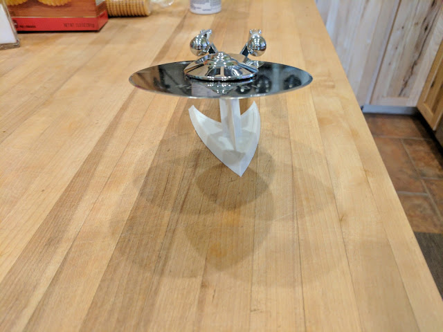
I used my 3D printer on a real project, the room temperature sensor. I spent a ton of time messing around with various drawing tools and learning a little about slicing software, but didn't actually do anything that could be considered useful. Unless you count a stand for my Star Trek Enterprise that I have on the kitchen window sill:
I got the files for the stand off Thingiverse <link> and just printed it. Thingiverse is wonderful for getting things that other people have worked on, but it isn't the same as coming up with your own idea and stepping through the entire process.
I decided on the basics of an enclosure for the sensor weeks ago, but it took a while to decide on a tool to use to design it, then the actual design process. I tested a couple of enclosure ideas for a few weeks and finally, a couple of days ago, put four more of the sensor electronics together and printed enclosures for all of them. I have five areas of the house being monitored and recorded in my home database that I can chart and examine.
Yes, they follow each other really well over the period charted, but remember, a temperature change of a small amount will make a room feel hot. It's interesting to watch this phenomenon. One room is 75F and the next is 78F, not enough to matter, but it feels really hot in the warmer room. It doesn't help much to put a thermometer in the warmer room so you can see the actual temperature; you just think the thermometer is wrong. Strange.
Here's what the entire assembly looks like on the wall:
It consists of a base plate that you mount to the wall and a cover that slides over the base to protect the wiring. Here's the two pieces before mounting:
Most of the engineers out there could have drawn this up in about 10 minutes, but frankly, this process was tough. Every little item had to be measured and thought out carefully. I had many, many test prints of sections to see if various things actually fit together. I kept running into little unexpected problems. The plastic would be a little too rough in some spots and pieces wouldn't fit together. The model would glue itself to the base of the printer and it flatly refused to come off. I didn't put holes in the sensor PC board and had to come up with a mounting solution for it. How tall EXACTLY should a stand off be for the various pieces?
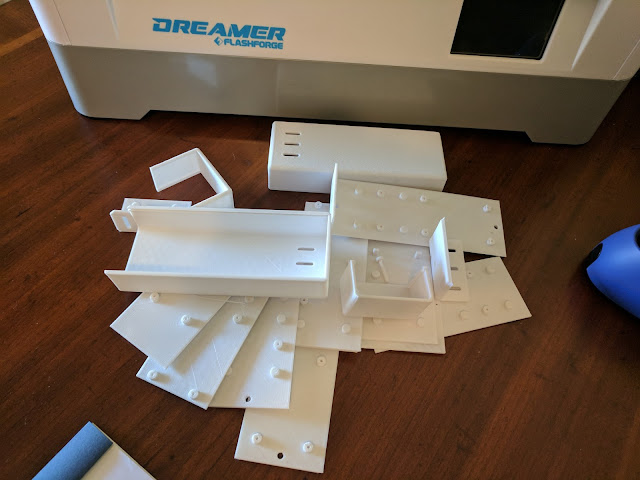
Most of this stuff was trial and error. Lots of errors. Just look at the pile of various attempts that will go in the trash after I post this:
One thing I discovered towards the end of the project was that I could cut the model and only print part of it. That was a real time saver. I could print the section I was trying to settle on and test it without waiting hours for the printer to finish the entire thing. I didn't read about using this capability anywhere on the web. Lots of folk talked about cutting the model, but didn't mention how it could be used to test a section of it. I guess most folk use 3D printers to make single piece items.
It's surprising how many little things creep up and have to be solved. The battery holder:
was initially a bit of a problem. I didn't want to mount it flat to the base plate because the mounting screws would go through the plastic, so I put in a couple of standoffs for the two screws that go through the holes in the middle of the assembly. Of course, that made it rock on the screws when I messed with the batteries. I solved that by putting in four more standoffs that kept it from moving.
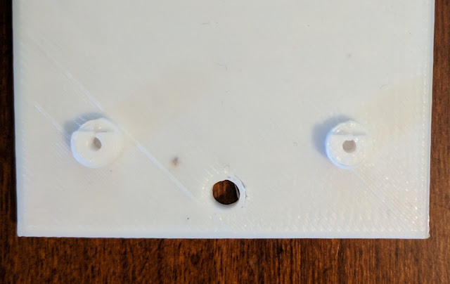
Th circuit board with the electronics on it didn't have holes for mounting screws (oops).
So I had to work out special standoffs that could hold the board in place. Of course I didn't have washers that would fit the standoffs, so I just printed them as part of the base. Here's what the base wound up looking like after I solved these problems:
The battery holder has six standoffs two of them for actual mounting and the others to keep it steady. The standoffs for the PC board have a cutout for the board and I use little washers to hold it down securely:
The little dark spot in the center-left is a moth that was attracted to the heat and became part of one of the sensors. Note to self: close the printer door stupid.
I slid the lid up on one of the sensors so I could show off the construction of the assemblies:
If you zoom in on the picture you'll be able to seee the mounting arrangement more closely. They were simple to install since they only take two #6 drywall screws and the entire device doesn't weigh much.
This project has been a lot of fun over the last couple of years. Yes, YEARS. And it isn't finished yet. I still want to use the sensors to replace the two house thermostats by taking the readings of each room and turning on heat, cool, or just fans to control the internal environment. I want to chart the outside temperature along with the rooms to see how it affects things as the day passes from season to season (notice, I only have two seasons here: nice and too-darn-hot). I may even create outdoor sensors to measure the wall temperature on some of the outside walls. That will prove the insulation effectiveness.
Who knows what I'll do with this in the future.


